Heat exchange fin and heat exchanger

A technology of heat exchange fins and heat exchangers, which is applied in the direction of heat exchanger types, indirect heat exchangers, heat exchange equipment, etc., can solve the problems of heat exchange performance decline, product volume increase, unfavorable heat exchange, etc., and achieve Improved thermal performance, increased heat transfer area, and improved heat transfer performance

Inactive Publication Date: 2015-05-06
HISENSE HOME APPLIANCES GRP CO LTD +1
View PDF7 Cites 11 Cited by
  • Summary
  • Abstract
  • Description
  • Claims
  • Application Information

AI Technical Summary

Problems solved by technology

[0003] The surface of heat exchanging fins in the prior art is usually relatively flat. When exchanging heat, along the direction of air flow, an air boundary layer will be formed on the surface of the heat exchanging fins, and as the air flows, the boundary layer will Gradually thickens, making it difficult for the surface of the heat transfer fin to fully contact with the flowing air, thus reducing the heat transfer performance
At present, in order to improve the heat transfer performance, the area of ​​the heat transfer fins is generally increased to increase the heat transfer area and improve the heat transfer p

Method used


Image

  • Heat exchange fin and heat exchanger
  • Heat exchange fin and heat exchanger
  • Heat exchange fin and heat exchanger

Examples


Example Embodiment

[0019] The technical solutions in the embodiments of the present invention will be clearly and completely described below in conjunction with the accompanying drawings in the embodiments of the present invention. Obviously, the described embodiments are only a part of the embodiments of the present invention, rather than all the embodiments. Based on the embodiments of the present invention, all other embodiments obtained by those of ordinary skill in the art without creative work shall fall within the protection scope of the present invention.
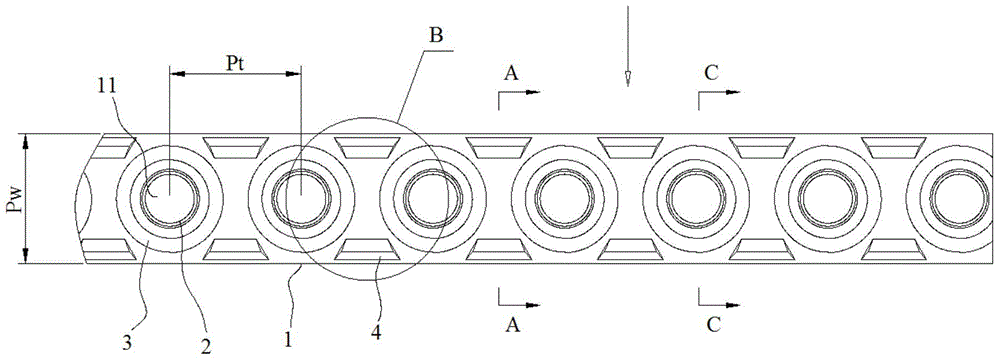
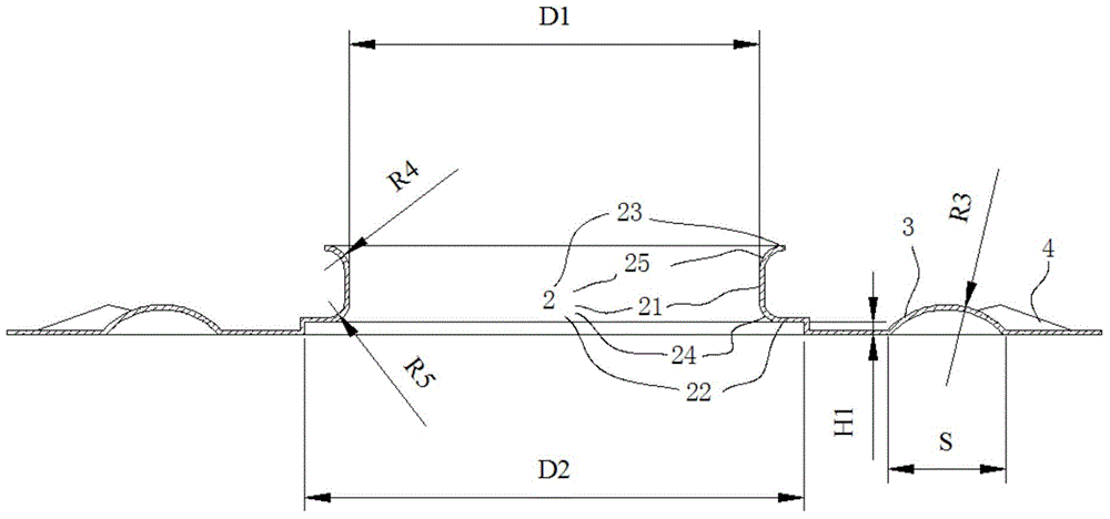
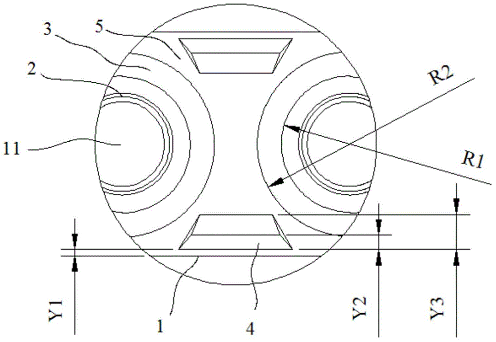
[0020] Reference Figure 1 ~ Figure 4 , figure 1 It is a specific embodiment of the heat exchange fin provided by the present invention. The heat exchange fin includes a substrate 1, a plurality of tube holes 11 are opened on the substrate 1, and a collar 2 is formed around the tube holes 11. The heat exchange tube (not shown in the figure) of the heat exchanger can be inserted into the collar 2 and the tube hole 11. A first protrusion 3 ...


PUM

PropertyMeasurementUnit
Heightaaaaaaaaaa
The inside diameter ofaaaaaaaaaa
Outer diameteraaaaaaaaaa

Abstract

The invention provides a heat exchange fin and a heat exchanger, and relates to the technical field of heat exchange devices. The heat exchange fin has the advantage that the heat exchange property can be improved. The heat exchange fin comprises a substrate and a plurality of pipe holes, wherein the pipe holes are formed in the substrate, a sleeve ring is formed around each pipe hole, a heat exchange pipe of the heat exchanger is arranged in each sleeve ring and the corresponding pipe hole in a penetrating way, a first convex part is formed on the substrate, is in a circle shape, and is arranged around each sleeve ring, and the inner diameter of each first convex part is greater than the outer diameter of the corresponding sleeve ring. The heat exchange fin is used for the heat exchanger.

Description

technical field [0001] The invention relates to the technical field of heat exchangers, in particular to a heat exchange fin and a heat exchanger. Background technique [0002] A heat exchanger is a device used in heating and refrigeration cycles, which can make the medium in it reach the required temperature by exchanging heat. At present, heat exchangers are widely used in air conditioners, heat pumps, and refrigerators. Among them, tube-fin heat exchangers are usually used in heat exchange equipment such as evaporators, condensers, and intercoolers of air-conditioners or heat pumps. Type heat exchangers generally include multiple heat exchange fins and multiple heat exchange tubes. There are multiple tube holes on the heat exchange fins, and the heat exchange tubes are installed in the tube holes. It flows outside the tube, conducts heat conduction between the heat exchange medium and the air through the tube wall and heat exchange fins, and realizes heat exchange. The f...

Claims


Application Information

Patent Timeline
IPC IPC(8): F28F1/30F28D1/04
Inventor 吴红霞陈绍楷刘忠民王伟戈
Owner HISENSE HOME APPLIANCES GRP CO LTD
Why Eureka
Try Eureka