Pantograph-catenary electric arc detection method and system based on train power supply system

A technology of a power supply system and a detection method, which is applied in the field of trains and can solve problems such as large energy consumption

Active Publication Date: 2015-05-06
CRRC QINGDAO SIFANG CO LTD
View PDF4 Cites 16 Cited by
  • Summary
  • Abstract
  • Description
  • Claims
  • Application Information

AI Technical Summary

Problems solved by technology

[0005] The main purpose of the present invention is to provide a pantograph-catenary arc detection method and system based on the train power supply system, to solve the problem in the pantograph-catenary arc simulation test method in the prior art, in order to generate high voltage and large current in the pantograph-catenary gap, High-voltage AC voltage source is used for power supply, resulting in technical problems of high energy consumption

Method used


Image

  • Pantograph-catenary electric arc detection method and system based on train power supply system
  • Pantograph-catenary electric arc detection method and system based on train power supply system
  • Pantograph-catenary electric arc detection method and system based on train power supply system

Examples


Embodiment 1

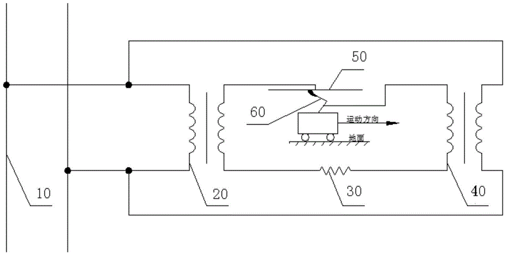
[0017] An embodiment of the present invention provides a pantograph-catenary arc detection method based on a train power supply system. Such as figure 1 As shown, the power supply system may include: a grid 10 , a step-up transformer 20 , a current limiting resistor 30 , a step-down transformer 40 , catenary conductors 50 , and a discharge circuit formed by a pantograph 60 .

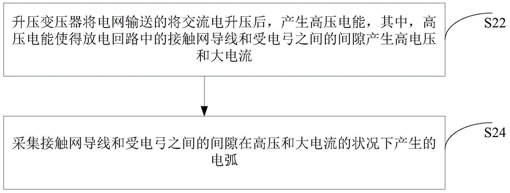
[0018] Such as figure 2 As shown, the method may include the following steps:

[0019] In step S22, the step-up transformer boosts the alternating current delivered by the grid to generate high-voltage electric energy, wherein the high-voltage electric energy causes the gap between the catenary wire and the pantograph in the discharge circuit to generate high voltage and large current.

[0020] Specifically, in this solution, the above-mentioned step-up transformer can transmit the high-voltage electric energy after the above-mentioned boost to the discharge circuit, that is, the step-up transformer 2...

Embodiment 2

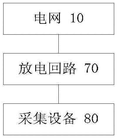
[0045] An embodiment of the present invention provides a pantograph-catenary arc detection system based on a train power supply system. Such as image 3 As shown, the system can include:

[0046] The grid 10 is used to transmit electric energy.

[0047] The discharge circuit 70 includes: a step-up transformer 20, a current-limiting resistor 30, a catenary wire 50, and a pantograph 60, wherein the step-up transformer 20 is used to boost the alternating current delivered by the power grid to generate high-voltage electric energy, wherein, The high-voltage electric energy makes the gap between the catenary conductor 50 and the pantograph 60 in the discharge circuit generate high voltage and large current.

[0048] The collection device 80 is used to collect the arc generated by the gap between the catenary wire and the pantograph under the condition of high voltage and high current.

[0049] Specifically, the above-mentioned step-up transformer can deliver the above-mentioned ...


PUM


Abstract

The invention discloses a pantograph-catenary detection method and system based on a train power supply system. The pantograph-catenary detection method and system based on the train power supply system includes that after a boosting transformer conducts boosting on alternating currents transmitted by the power grid, high-voltage electric energy is generated and enables the clearance between a catenary wire and a pantograph in a discharge loop to generate high voltage and large currents; and electric arcs generated from the clearance between the catenary wire and the pantograph under the condition of high voltage and large currents are collected. Therefore, the technical problem that large energy consumption is caused by the power supply through a high-voltage AC voltage source in order to generate high voltage and large currents from the pantograph-catenary clearance in a pantograph-catenary simulation test in the prior art is solved.

Description

technical field [0001] The invention relates to the field of trains, in particular to a pantograph-catenary arc detection method and system based on a train power supply system. Background technique [0002] In recent years, with the rapid development of high-speed railways, the principle of obtaining electric energy for high-speed trains is: to obtain electric energy from the catenary through the sliding contact between the catenary wire and the pantograph slide. However, with the increase of train speed, the coupling vibration intensifies during the contact between the catenary and the pantograph, which seriously deteriorates the electrical contact state between the pantograph and the catenary, resulting in the Off-line occurs frequently, and the pantograph-catenary arc generated during off-line causes severe ablation of the catenary wire and pantograph slide, which poses a huge threat to the safety of high-speed railways and has become a technical bottleneck restricting th...

Claims


Application Information

Patent Timeline
Patent Type & Authority Applications(China)
IPC IPC(8): G01R31/00G01R31/50
CPCB60L5/18B60L9/08G01R31/008G01R31/14G01R31/50G01R31/00G01R31/005G01R31/40
Inventor 贾步超焦京海侯方东由建宏于治国周海军杨盼奎
Owner CRRC QINGDAO SIFANG CO LTD
Why Eureka
Try Eureka