Eureka AIR delivers breakthrough ideas for toughest innovation challenges, trusted by R&D personnel around the world.

Connecting structure for cascading folded waveguide

A connection structure and folded waveguide technology, which is applied in the direction of traveling wave tubes, the introduction arrangement of transit time electron tubes, the coupling device of transit time electron tubes, etc., can solve the problem of reducing the application range of multi-bundle folded waveguide traveling wave tubes, Increase the size and weight of the traveling wave tube, application restrictions, etc., to achieve the effect of improving the weight, improving the large space occupied, and reducing the connection size

Active Publication Date: 2015-05-06
UNIV OF ELECTRONICS SCI & TECH OF CHINA
View PDF2 Cites 5 Cited by
  • Summary
  • Abstract
  • Description
  • Claims
  • Application Information

AI Technical Summary

Problems solved by technology

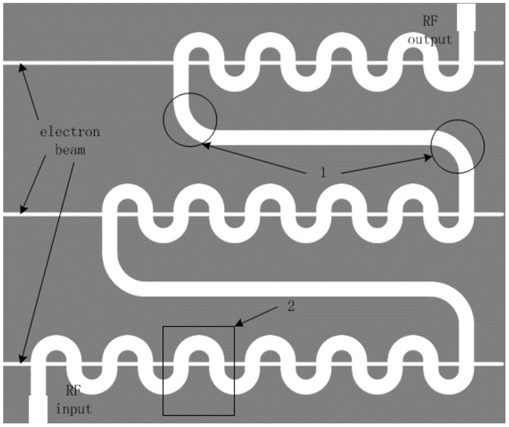
However, the multi-beam folded waveguide traveling wave tube in the article adopts arc-shaped curved waveguide connection between the stages, and its bending radius is generally required to meet r≥1.5b (b is the width of the narrow side of the folded waveguide cross-section), so this arc The shape of the curved waveguide makes the distance between the two stages larger, which increases the size and weight of the traveling wave tube, which reduces the application range of the multi-bundle folded waveguide traveling wave tube, and its application is limited in some occasions

Method used


Image

  • Connecting structure for cascading folded waveguide
  • Connecting structure for cascading folded waveguide
  • Connecting structure for cascading folded waveguide

Examples


Embodiment Construction

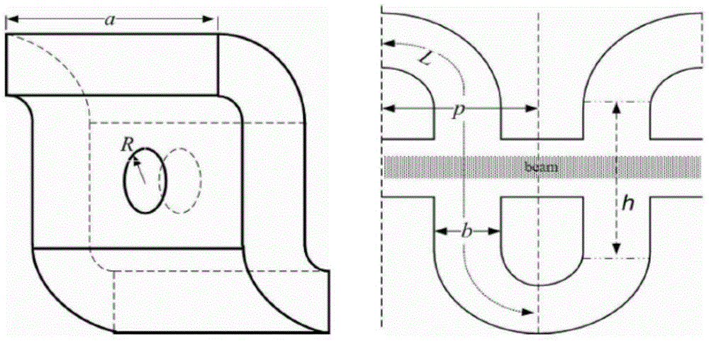
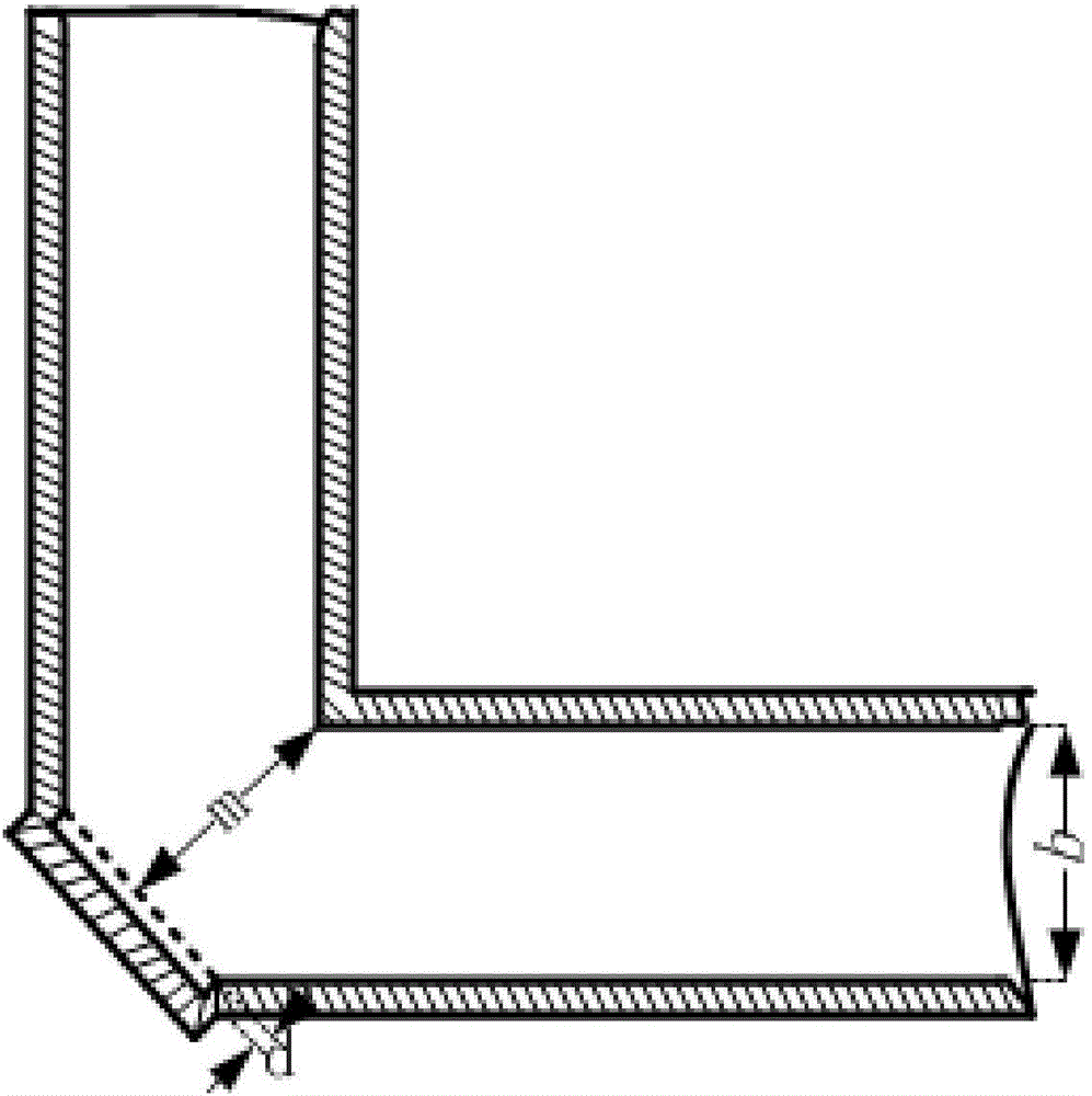
[0011] A design and application of a connection structure for the cascading of three-injection cascaded folded waveguide traveling wave tubes in the Ka band (. The overall schematic diagram of the three-injection cascaded folded waveguide traveling wave tube is shown in figure 1 As shown, the number 1 in the figure is the arc-shaped curved waveguide of the background technology, and the number 2 is a period of the folded waveguide, and its enlarged structure schematic diagram is shown in figure 2 As shown, the following dimensions are set: the cross-sectional dimension of the folded waveguide is a*b (length*width), where a=4.92mm, b=0.90mm, the length of half a period of the folded waveguide is p=1.76mm, and the folded waveguide The height of the non-curved part is h=1.25mm, and the radius of the electron injection channel is R=0.5mm. Using the connection structure of the present invention to replace the original arc-shaped curved waveguide, as shown in Figure 3, the distance...


PUM


Abstract

The invention discloses a connecting structure for cascading folded waveguide, and belongs to the field of microwave electron vacuum. The connecting structure is in a form of a bent rectangular waveguide and is characterized in that the bending angle of the bent rectangular waveguide is 90 degrees, and the outer folding angle of the bent part outwards extends to form a rectangular cavity; the connecting structure is a full-metal structure. The connecting structure has a good input / output feature; the connection size of the cascading folded waveguide travelling wave tubes at all levels is reduced to some extent, and therefore, the travelling wave tubes are compact in structure and light in weight, and as a result, the applicable scope of a plurality of folded waveguide travelling wave tube bundles is expanded.

Description

technical field [0001] The invention belongs to the field of microwave electric vacuum, and in particular relates to a connection structure for cascade folded waveguides. Background technique [0002] The folded waveguide slow wave structure has the advantages of high power, wide frequency band, and high gain. Slow-wave circuits as high-frequency, high-power, broadband microwave sources have great application potential. Its main advantage is that it solves the contradiction between high power and wide frequency band that millimeter wave devices have not overcome for a long time, and realizes the unity of the two. However, with the development of microwave technology and the increase of application frequency, the power gain of a single folded waveguide traveling wave tube can no longer meet the demand. Although the gain of the traveling wave tube can be increased by increasing the length of the slow wave line, this will increase the overall size and weight of the tube, whic...

Claims


Application Information

Patent Timeline
Patent Type & Authority Applications(China)
IPC IPC(8): H01J25/34H01J23/34
CPCH01J23/14H01J23/38
Inventor 尹俊辉徐立诸葛天祥李斌
Owner UNIV OF ELECTRONICS SCI & TECH OF CHINA
Why Eureka
Eureka Blog
Learn More