
A universal antenna flange and an antenna conversion device containing the flange

An antenna conversion and universal technology, applied in the direction of antennas, electrical components, etc.

Active Publication Date: 2017-08-04
BEIJING INST OF RADIO METROLOGY & MEASUREMENT
View PDF2 Cites 0 Cited by
  • Summary
  • Abstract
  • Description
  • Claims
  • Application Information

AI Technical Summary

Problems solved by technology

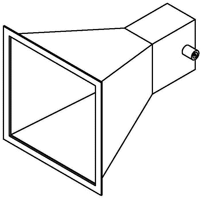
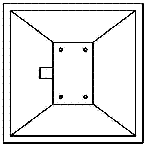
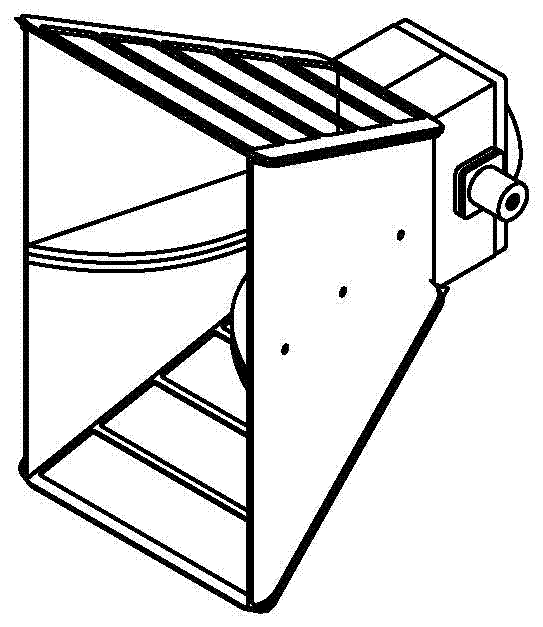
[0005] The technical problem to be solved by the present invention is to provide a universal antenna flange, which solves the problem of simple switching of various tested probe antennas in the quiet zone test of the compact field, and at the same time improves the working efficiency and reliability of the quiet zone detection. sex

Method used


Image

  • A universal antenna flange and an antenna conversion device containing the flange
  • A universal antenna flange and an antenna conversion device containing the flange
  • A universal antenna flange and an antenna conversion device containing the flange

Examples


Embodiment 1

[0039] see Figure 11-Figure 20 As shown, a universal antenna flange includes a disc body 1 with a central protruding shaft 11, and five antenna interface boards 12, 13, 14, 15 are extended to the outer edge of the disc body 1. , 16, the plane where the antenna interface board is located and the plane of the disc body 1 form an obtuse angle structure, the antenna polarization axis of each antenna interface board intersects with the central axis of the disc body 1 at the same focal point, and the center axis of the disc body 1 A positioning hole 17 is provided on the outer periphery of the central protruding shaft 11 corresponding to each antenna interface board, and the center of the positioning hole 17 is located on the projection line of the antenna polarization axis of the corresponding antenna interface board on the disk body 1 .

[0040]The disc body 1 is provided with five antenna interface boards 12, 13, 14, 15, and 16 respectively, which are 0.3GHz-1GHz receiving anten...

Embodiment 2

[0046] A universal antenna flange, which is different from Embodiment 1 in that the angle α between the plane where the antenna interface board is located and the plane of the disc body 1 is 110°.

[0047] A universal antenna switching device, which is different from Embodiment 1 in that the angle β between the slope surface 211 of the scanning head 21 and the horizontal plane is 20°.

Embodiment 3

[0049] A universal antenna flange, which is different from Embodiment 1 in that the angle α between the plane where the antenna interface board is located and the plane of the disc body 1 is 120°.

[0050] A universal antenna switching device, which is different from Embodiment 1 in that the angle β between the slope surface 211 of the scanning head 21 and the horizontal plane is 30°.


PUM


Abstract

The invention relates to a universal antenna flange, which includes a disc body with a central protruding shaft, at least one antenna interface plate is extended on the outer edge of the disc body, and the plane where the antenna interface plate is located An obtuse angle structure is formed between the plane of the disk body, the antenna polarization axis of each antenna interface board intersects with the central axis of the disk body at the same focal point, and the outer edge of the central convex axis of the disk body corresponds to each antenna interface board A positioning hole is provided, and the center of the positioning hole is located on the projection line of the antenna polarization axis of the corresponding antenna interface board on the disk; a universal antenna conversion device includes a universal antenna flange and a scanning frame , the flange plate can be rotatably connected to the slope of the scanning frame; the invention solves the problem of simple switching of various probe antennas under test in the quiet zone test of the compact field, and at the same time improves the working efficiency and reliability of the quiet zone detection.

Description

technical field [0001] The invention relates to a flange device, in particular to a universal antenna flange and an antenna conversion device containing the flange. Background technique [0002] The compact field is a device that uses a precise reflector or microwave lens to convert the spherical wave emitted by the feed source into a plane wave within a short distance. The quasi-plane wave generated by it can fully meet the environmental requirements of the antenna, radome electromagnetic characteristics and target RCS test . [0003] Usually, the probe scanning method is used to calibrate the performance of the quiet zone in the tight field, and the standard probe antenna is used to directly test and evaluate the amplitude and phase of the plane wave field in the tight field test area. [0004] see Figure 1-Figure 10 As shown, the frequency coverage of the compact field test is from 0.3GHz to 40GHz, and the frequency band is very wide. One antenna cannot cover the entire...

Claims


Application Information

Patent Timeline
Patent Type & Authority Patents(China)
IPC IPC(8): H01Q3/02
Inventor 黄建领马永光黄承祖
Owner BEIJING INST OF RADIO METROLOGY & MEASUREMENT
Learn More