High frequency connector

A technology of high-frequency connectors and grounding strips, which is applied in the direction of connection, parts of connection devices, electrical components, etc., and can solve problems such as deformation of shrapnel, affecting the contact stability of grounding strips, and strong signal interference.

Active Publication Date: 2016-08-24
DONGGUAN TECONN ELECTRONICS TECH CO LTD
View PDF7 Cites 0 Cited by
  • Summary
  • Abstract
  • Description
  • Claims
  • Application Information

AI Technical Summary

Problems solved by technology

[0002] The current connector has gradually developed into an ultra-thin type, and undoubtedly the distance between the upper and lower rows of contact terminals has also been further reduced, resulting in stronger signal interference between the contact terminals, which is not conducive to the transmission of high-frequency signals; The way is to set the grounding piece to form a better shielding effect when the plug and socket are connected to each other and improve the anti-interference ability. However, the shrapnel on the traditional grounding piece is likely to be caused by large stress during the multiple insertion and extraction process. The shrapnel is deformed, so it affects the contact stability of the ground sheet, and the shielding effect is difficult to guarantee, which affects the transmission stability of high-frequency signals

Method used


Image

  • High frequency connector
  • High frequency connector
  • High frequency connector

Examples


Embodiment Construction

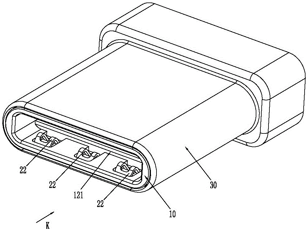
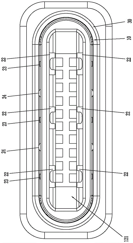
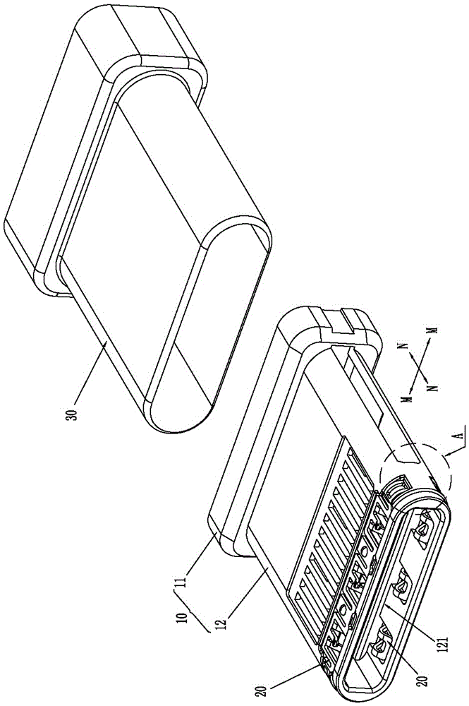
[0036] Please refer to Figure 1 to Figure 7 As shown, it shows the specific structure of the embodiment of the present invention. Here, a high-frequency plug connector is taken as an example for illustration; it includes an insulating body 10, contact terminals (not shown in the figure), grounding sheet 20 and shielding shell 30, the insulating body 10 includes a base 11 and a tongue 12 integrally connected to the front side of the base 11, the front end of the tongue 12 is concavely provided with a slot 121, and the aforementioned contact terminals are exposed on the Inside slot 121.

[0037] The grounding piece 20 is set against the front end of the slot 121, and the grounding piece 20 is located on the front side of the contact terminal, and only the upper side surface or only the lower side surface or the upper and lower side surfaces of the tongue plate 12 are recessed towards the slot 121. There is an installation concave cavity 122 for setting the grounding sheet 20, ...


PUM


Abstract

The invention discloses a high-frequency connector. The high-frequency connector comprises an insulating body, a contact terminal, a grounding lug and a shielding case. The insulating body comprises a base and a tongue plate, the front end surface of the tongue plate is recessed backwards to form an inserting slot, and the contact terminal is exposed inside the inserting slot; the grounding lug is arranged corresponding to the front part of the inserting slot and on the front side of the contact terminal; the ground lug comprises a base plate part, a plurality of first spring pieces, a plurality of second spring pieces and a plurality contact protrusions, wherein the first spring pieces, the second spring pieces and the contact protrusions are integrally formed from the base plate part through stamping; every first spring piece is provided with a first elastic butting part, which is protruded towards the inserting slot and exposed inside the inserting slot,, and the first spring piece is provided with a second yielding through slot communicating the upper surface and the lower surface of the base plate part; every second spring piece is suspended inside the corresponding second yielding through slot; the contact protrusions are formed between every two neighboring two first spring pieces; the shielding case wraps the outer surface of the tongue plate; the second spring pieces and the contact protrusions are pressed by the shielding case and electrically abut against the inner wall of the shielding case to effectively disperse stress of the grounding lug during insertion and extraction and further to avoid deformation of the first spring pieces due to overlarge stress.

Description

technical field [0001] The invention relates to the technology in the field of connectors, in particular to a high-frequency connector. Background technique [0002] The current connector has gradually developed into an ultra-thin type, and undoubtedly the distance between the upper and lower rows of contact terminals has also been further reduced, resulting in stronger signal interference between the contact terminals, which is not conducive to the transmission of high-frequency signals; The way is to set the grounding piece to form a better shielding effect when the plug and socket are connected to each other and improve the anti-interference ability. However, the shrapnel on the traditional grounding piece is likely to be caused by large stress during the multiple insertion and extraction process. The deformation of the shrapnel affects the contact stability of the ground sheet, and the shielding effect is difficult to be guaranteed, which affects the transmission stabili...

Claims


Application Information

Patent Timeline
Patent Type & Authority Patents(China)
IPC IPC(8): H01R13/646H01R13/6583H01R13/629
CPCH01R13/629H01R13/646H01R13/6583
Inventor 孙鸿运李胡彬
Owner DONGGUAN TECONN ELECTRONICS TECH CO LTD
Why Eureka
Try Eureka