Power distribution cabinet

A technology for power distribution cabinets and cabinets, which is applied in the direction of substation/distribution device casing, substation/switchgear cooling/ventilation, etc. problem, to achieve the effect of easy replacement and easy processing

Inactive Publication Date: 2015-05-06
GUIZHOU CHANGTONG ELECTRIC
View PDF8 Cites 6 Cited by
  • Summary
  • Abstract
  • Description
  • Claims
  • Application Information

AI Technical Summary

Problems solved by technology

[0002] Power distribution cabinets are often installed in outdoor environments. For areas with high humidity, moisture-proof design for power distribution cabinets is required. At present, moisture-proof depends on fans alone, but the area of ​​action of fans is limited. For environments with very high humidity, fans cannot play a role. Good overall moisture-proof effect, even water vapor will condense on the inner wall of the power distribution cabinet to form water droplets and flow to the ground inside the cabinet, which is very dangerous to the electrical equipment in the power distribution cabinet
[0003] At the same time, the power distribution cabinet is generally relatively large in size, and the strength of the cabinet door is not enough. The traditional method is to use reinforcing ribs alone, which occupy most of the space of the cabinet door. If desiccant needs to be placed on the cabinet door, additional design is required. Dedicated deployment device

Method used


Image

  • Power distribution cabinet
  • Power distribution cabinet
  • Power distribution cabinet

Examples


Embodiment Construction

[0021] Embodiments of the present invention will be described below with reference to the drawings.

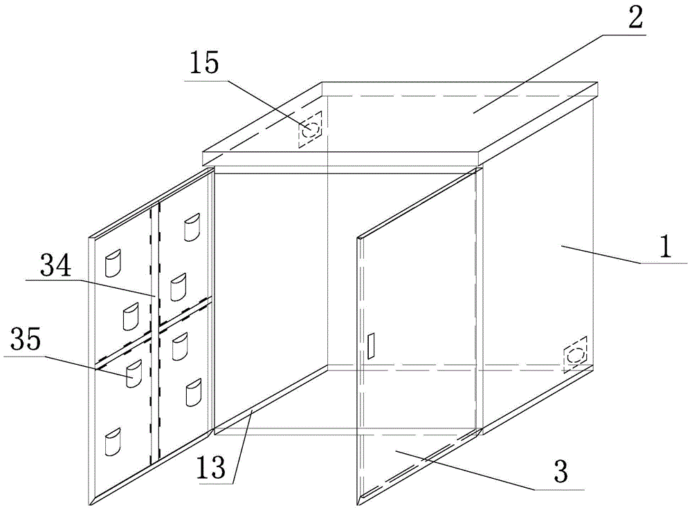
[0022] The invention provides a power distribution cabinet, such as figure 1 As shown, the power distribution cabinet includes a cabinet body 1 and a top cover 2 and a cabinet door 3 arranged on the cabinet body 1 .

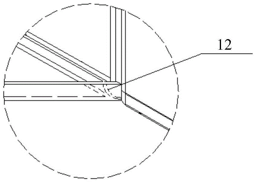
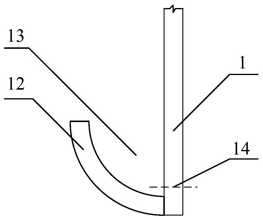
[0023] The bottoms of the three inner walls of the cabinet 1 are respectively provided with laterally extending cabinet drainage channels 13 , and the cabinet body at the position of the cabinet drainage channels 13 is provided with cabinet drainage holes 14 . In this embodiment, the drainage channel of the cabinet body is realized by using 1 / 4 round pipe combined with the wall surface. Such as figure 2 As shown, the 1 / 4 round pipe 12 has two straight sides and two arc sides, and the two ends can be provided with stoppers or blocked by other structures in the cabinet to prevent water from flowing out. Such as image 3 As shown, one of the straight sides of t...


PUM


Abstract

The invention discloses a power distribution cabinet. The power distribution cabinet can solve the problem of moisture as well as be reinforced, and reduce the possibility of harming the electrical equipment by water drops dripping on the floor inside the cabinet along the wall surface. The bottom of the inner wall surface of the cabinet body is provided with cabinet body drainage channels; a cabinet body drainage hole is opened at the cabinet body drainage channel; two fans are arranged on two opposite sides at the rear portion of the cabinet body, one fan is arranged higher, the other is lower; the inner side of each cabinet door is provided with reinforcing ribs which are arranged in a cross shape; the areas of the inner side of the cabinet door without the reinforcing ribs are provided with reinforcing blocks which are distributed along the diagonal line of the cabinet door; the reinforcing blocks are hollow semi-cylindrical shells; surfaces of the shells are provided with through holes; rectangular open surfaces of the semi-cylindrical shells are snapped on the cabinet door; one ends of the semi-cylindrical shells are semicircular openings and opened upwardly, the other ends are semicircular bottom surfaces and closed downwardly; packaged drying agents are filled in the semi-cylindrical shells from the openings.

Description

technical field [0001] The invention relates to the technical field of power distribution cabinet design. Background technique [0002] Power distribution cabinets are often installed in outdoor environments. For areas with high humidity, moisture-proof design for power distribution cabinets is required. At present, moisture-proof depends on fans alone, but the area of ​​action of fans is limited. For environments with very high humidity, fans cannot play a role. Good overall moisture-proof effect, even water vapor will condense on the inner wall of the power distribution cabinet to form water droplets and flow to the ground inside the cabinet, which is very dangerous to the electrical equipment in the power distribution cabinet. [0003] At the same time, the power distribution cabinet is generally relatively large in size, and the strength of the cabinet door is not enough. The traditional method is to use reinforcing ribs alone, which occupy most of the space of the cabin...

Claims


Application Information

Patent Timeline
Patent Type & Authority Applications(China)
IPC IPC(8): H02B1/26H02B1/56H02B1/28
CPCH02B1/28H02B1/26
Inventor 张钊张晖李贵祥杨运富
Owner GUIZHOU CHANGTONG ELECTRIC
Why Eureka
Try Eureka