
FPGA (Field Programmable Gate Array) based video image compensating method and device

A compensation method and video image technology, applied in the field of video transmission, can solve the problems of complex development and implementation process, low system stability, limited adjustment range, etc., and achieve the effect of improving video experience, reducing costs, and having no adjustment range.

Inactive Publication Date: 2015-05-06
深圳市载德光电技术开发有限公司
View PDF7 Cites 3 Cited by
  • Summary
  • Abstract
  • Description
  • Claims
  • Application Information

AI Technical Summary

Problems solved by technology

[0004] The technical problem to be solved by the present invention is that, aiming at the defects of the prior art that affect the user’s video experience, the adjustment range is limited, a dedicated chip must be used, the development and implementation process is relatively complicated, the system’s stability is not high, and the cost is high, it provides An FPGA-based video image compensation method and device that improves the user's video experience, has no limit to the adjustment range, does not need to use a dedicated chip, reduces the complexity of the development and implementation process, improves system stability, and reduces costs

Method used


Image

  • FPGA (Field Programmable Gate Array) based video image compensating method and device
  • FPGA (Field Programmable Gate Array) based video image compensating method and device
  • FPGA (Field Programmable Gate Array) based video image compensating method and device

Examples


Embodiment Construction

[0036] The following will clearly and completely describe the technical solutions in the embodiments of the present invention with reference to the accompanying drawings in the embodiments of the present invention. Obviously, the described embodiments are only some, not all, embodiments of the present invention. Based on the embodiments of the present invention, all other embodiments obtained by persons of ordinary skill in the art without creative efforts fall within the protection scope of the present invention.

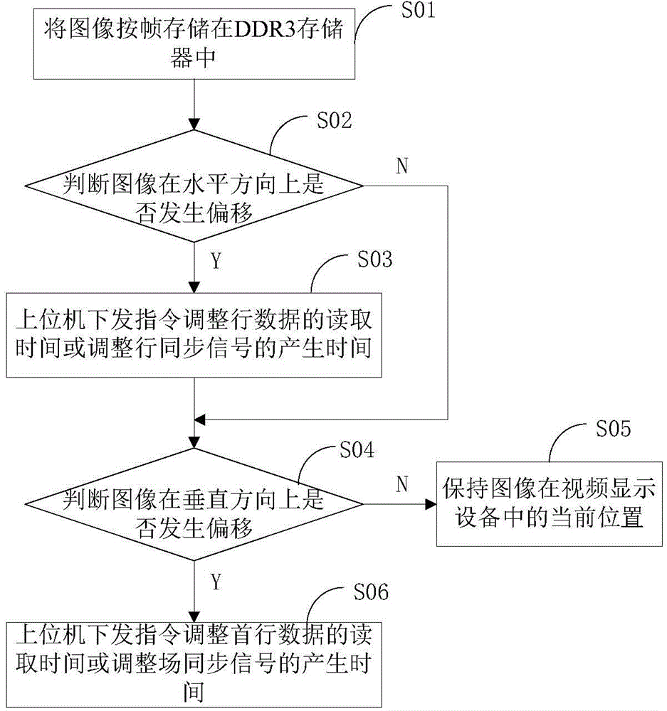
[0037] In the FPGA-based video image compensation method and device embodiment of the present invention, the flow chart of the FPGA-based video image compensation method is as follows figure 1 shown. In this embodiment, the FPGA is plugged with a DDR3 memory, and the inside of the FPGA is provided with a DDR3 controller. figure 1 In, this FPGA-based video image compensation method comprises the steps:

[0038] Step S01 stores the image frame by frame in the DDR3 ...


PUM


Abstract

The invention provides FPGA (Field Programmable Gate Array) based video image compensating method and device. The device is a DDR3 storage is hung to the outside of the FPGA. The method comprises the steps of storing the images into the DDR3 storage according to frame; determining whether the images are deviated in the horizontal direction; if so, distributing an instruction by a host computer to adjust the reading time of the line data or adjusting the generation time of the line synchronizing signals and carrying out the next step; if not so, carrying out the next step; determining whether the images are deviated in the vertical direction; if so, distributing an instruction by a host computer to adjust the reading time of the first line data or adjusting the generation time of the field synchronizing signals; if not so, remaining the images at the current position in a video display device. The FPGA based video image compensating method and device have the beneficial effects that the user video experience is increased; the adjusting range is out of limitation; special chips are not used; the complexity of development implementation can be reduced; the stability of the system is improved; the cost is reduced.

Description

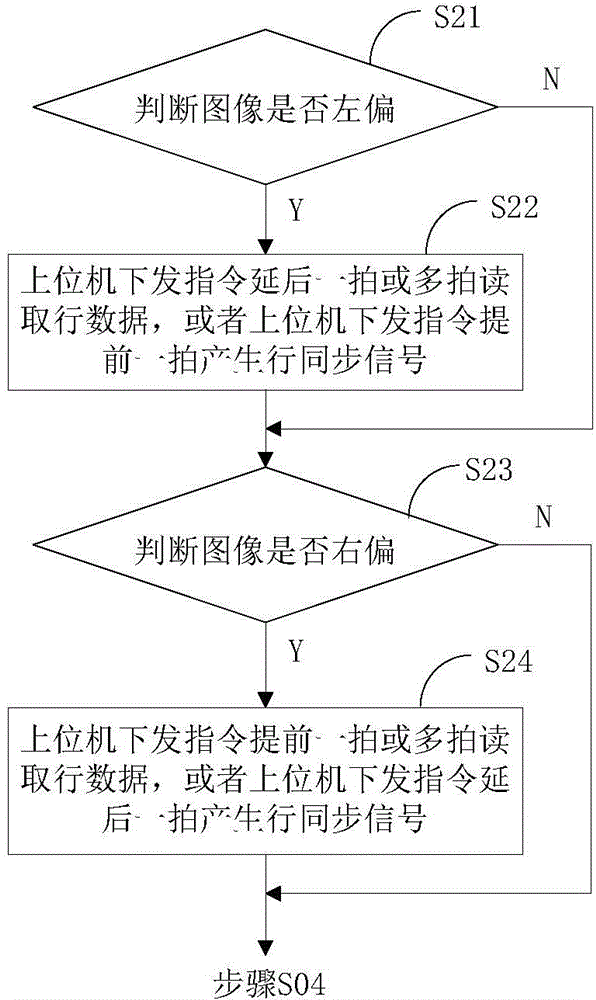
technical field [0001] The invention relates to the field of video transmission, in particular to an FPGA-based video image compensation method and device. Background technique [0002] In the field of video transmission and display, VGA is still widely used as an analog video signal, but due to the attenuation in the transmission of analog signals, it is easy to be interfered, so that the video screen finally presented on the display device has a frame deviation, or left deviation. Or right, or upward, or downward, which brings a very bad video experience to users. [0003] Therefore, it is necessary to adjust and compensate the video frame to adjust the picture to the middle of the video display device. The existing technology is realized by a dedicated analog chip, and the adjustment range of the up, down, left, and right directions of the screen is limited or only supports a single-dimensional adjustment. It is more complex and therefore affects the stability of the sy...

Claims


Application Information

Patent Timeline
Patent Type & Authority Applications(China)
IPC IPC(8): H04N7/01G09G5/393
Inventor 李鹏肖园周福明
Owner 深圳市载德光电技术开发有限公司
Learn More