
Solvent extraction settler arrangement

A settling tank and extraction technology, applied in the field of solvent extraction settling tank equipment, to achieve the effects of less dirt accumulation, lower solution cost, and lower oxidation degree

Inactive Publication Date: 2015-05-06
OUTOTEC FINDLAND OY
View PDF7 Cites 0 Cited by
  • Summary
  • Abstract
  • Description
  • Claims
  • Application Information

AI Technical Summary

Problems solved by technology

A disadvantage of the constant section of the discharge channel is also that the structure of the discharge channel includes excess material that is not actually needed

Method used


Image

  • Solvent extraction settler arrangement
  • Solvent extraction settler arrangement
  • Solvent extraction settler arrangement

Examples


Embodiment Construction

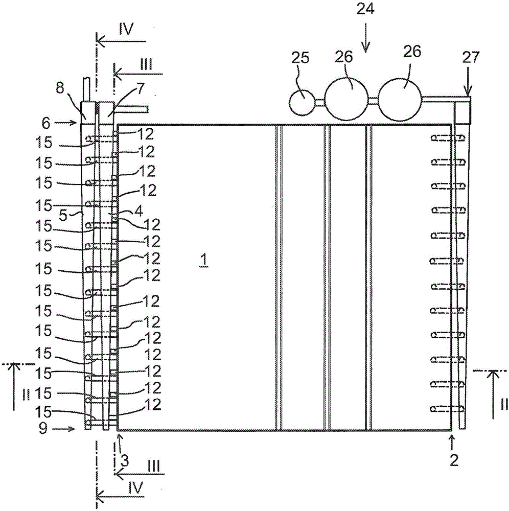
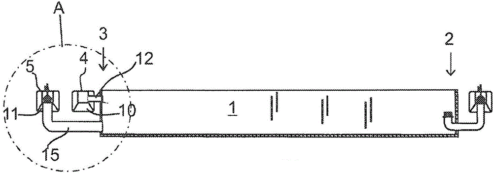
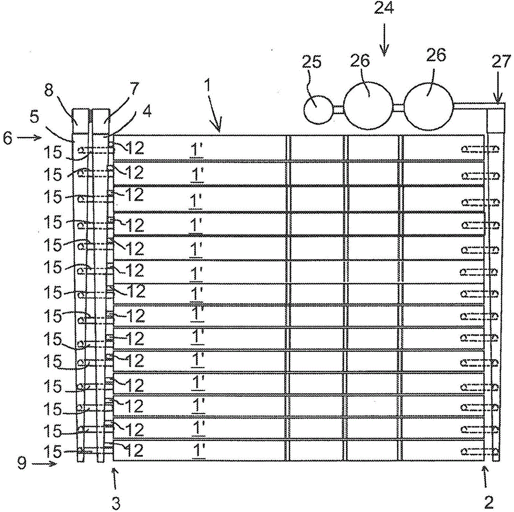
[0030] figure 1 with 3 A solvent extraction settling tank apparatus suitable for a hydrometallurgical liquid-liquid extraction process is shown.

[0031] The settling tank apparatus comprises a mixing unit 24 for preparing dispersions from mutually immiscible solutions. In this case, the mixing unit 24 comprises a pumping unit 25 and two mixers 26 . The settling tank 1 is arranged to separate the solution phase from the dispersion supplied at the feed end 2 while the dispersion flows towards the discharge end 3 . A feed device 27 is arranged at the feed end 2 for feeding the dispersion prepared by the mixing unit 24 to the settling tank 1 .

[0032] Elongated discharge channels 4 and 5 are arranged at the discharge end 3 to collect and discharge the separated solution. Each discharge chute 4 , 5 comprises a first end 6 , an outlet 7 , 8 arranged at the first end 6 , and a closed second end 9 .

[0033] as in figure 1 , 2 , 4 and 5, the two discharge grooves 4, 5 have th...


PUM


Abstract

A solvent extraction settler arrangement comprises a settler (1) having a feed end (2) and a discharge end (3), said settler being arranged to separate solution phases from a dispersion fed from the feed end while the dispersion flows to the discharge end. Elongated discharge launders (4, 5) are arranged at the discharge end (3) of the settler for each solution phase to be separated from the dispersion, each discharge launder (4, 5) including a first end (6), an outlet (7, 8) arranged at the first end, and a closed second end (9). At least one of the discharge launders (4, 5) has a form of a conical tube with a cross-section converging from the first end (6) towards the second end (9) and an inclined bottom (10, 11) descending from the second end (9) towards the first end (6).

Description

technical field [0001] The invention relates to solvent extraction settling tank equipment suitable for hydrometallurgical liquid-liquid extraction process. Background technique [0002] Solvent extraction settling tank apparatus are known, as disclosed in, for example, publications WO97 / 40899 and WO97 / 40900, suitable for hydrometallurgical liquid-liquid extraction processes and typically include Mixing unit for preparing dispersions. The settling tank is arranged to separate the solution phase from the dispersion supplied at the feed end while the dispersion flows to the discharge end of the settling tank. An elongated discharge trough is arranged at the discharge end of the settling tank to receive the solution phases from the settling tank and to discharge each solution phase separated from the dispersion in the settling tank. Each drain trough includes a first end and a closed second end, the outlet being disposed at the first end. [0003] In known technology, the di...

Claims


Application Information

Patent Timeline
Patent Type & Authority Applications(China)
IPC IPC(8): C22B3/02C22B3/20B01D11/04
CPCC22B3/02B01D11/0449B01D11/0484B01D17/0214Y02P10/20B01D11/04C22B3/20B01D17/0208
Inventor J·瓦尔诺R·萨里奥H·弗雷德里克松
Owner OUTOTEC FINDLAND OY
Learn More