
Stainless steel sheet wire-drawing device for controlling wire-drawing stroke

A stainless steel and plate technology, applied in the direction of manufacturing tools, metal processing equipment, metal processing, etc., can solve problems such as visual fatigue, large errors, safety accidents, etc., and achieve the effect of reducing labor intensity

Active Publication Date: 2015-05-13
台山市誉美厨卫制品有限公司
View PDF5 Cites 1 Cited by
  • Summary
  • Abstract
  • Description
  • Claims
  • Application Information

AI Technical Summary

Problems solved by technology

[0003] The purpose of the present invention is to overcome the problems that the above-mentioned wire drawing stroke of the existing wire drawing equipment is controlled by the naked eye by the operator based on experience, the error is large, and it requires mental concentration, which is easy to cause visual fatigue and cause safety accidents, and designs a control wire drawing stroke The stainless steel plate wire drawing device, which monitors and displays the wire drawing stroke by setting sensors, can facilitate people to accurately control the wire drawing distance, without checking the wire drawing stroke with the naked eye, reduces labor intensity, is safer, and solves the problem of the wire drawing stroke of the existing wire drawing equipment It is the operator who controls with the naked eye based on experience, the error is large, and it requires concentration, which is easy to cause visual fatigue and cause safety accidents.

Method used


Image

  • Stainless steel sheet wire-drawing device for controlling wire-drawing stroke

Examples


Embodiment 1

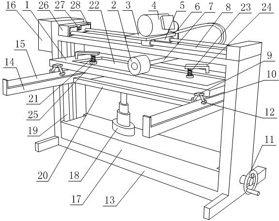
[0012] Such as figure 1As shown, the stainless steel plate wire drawing device for controlling the wire drawing stroke includes an internal hollow support frame 13, a support platform 1 is arranged in the cavity of the support frame 13, and a limit frame is arranged below the support platform 1, and the support platform 1 can move along the Sliding horizontally against the limit frame, the top surface of the support platform 1 is concaved to form a mounting groove 22, and the center of the mounting groove 22 is set on the center line of the support platform 1, and the top surface of the support platform 1 is provided with several support arms. 24. The bottom ends of the support arms 24 are all fixed to the top surface of the support platform 1. The support arms 24 are in an L-shaped structure. The support arms 24 are all provided with compression springs 23. Fixed, the compression springs 23 are all arranged directly above the installation groove 22, and the compression spring...


PUM


Abstract

The invention discloses a stainless steel sheet wire-drawing device for controlling the wire-drawing stroke. A supporting platform is arranged in a supporting rack, a limiting rack is arranged below the supporting platform, the supporting platform is sunken inward to form a mounting groove, a supporting arm is arranged on the supporting platform, a compression spring is arranged on the supporting arm, a compression column is arranged in the compression spring, a compression disc is arranged at the bottom end of the compression column, a hydraulic box is arranged in the supporting rack, and a plurality of flexible arms are arranged in the hydraulic box; a guide rod is sleeved by a guide cover which is provided with a supporting plate, the supporting plate is fixedly provided with a motor, the supporting rack is provided with a control box, the control box is connected with the motor, an anti-collision pad is arranged on the limiting base, a distance sensor is arranged in the limiting base, a wire-drawing brush is arranged in the supporting rack, a central shaft is arranged in the wire-drawing brush, and the central shaft is provided with a belt in a sleeving manner. The device monitors and displays the wire-drawing stroke by arranging the sensor, so that people can precisely control the wire-drawing distance conveniently, the labor intensity is reduced, and the device is relatively safe.

Description

technical field [0001] The invention relates to a device, in particular to a stainless steel plate wire drawing device for controlling the wire drawing stroke. Background technique [0002] The wire drawing process is a metal processing process. In metal pressure processing. Under the action of external force, the metal is forced to pass through the mold, the metal cross-sectional area is compressed, and the technical processing method to obtain the required cross-sectional area shape and size is called the metal wire drawing process. A tool that changes shape and size is called a wire drawing die. In order to break through the limitations of designers on the use of decorative materials and meet more creative needs, human beings affirm themselves and explore the unknown in the new century, and develop and design gold and silver brushed finishes that combine the power of knowledge and the spirit of science and technology. Metal plate. Such products have gold brushed, silve...

Claims


Application Information

Patent Timeline
Patent Type & Authority Applications(China)
IPC IPC(8): B21C1/02
CPCB21C1/02B21C51/00
Inventor 刘开亮
Owner 台山市誉美厨卫制品有限公司
Learn More