
Swing Marble Multi-wire Cutting Machine

A multi-wire cutting machine and marble technology, applied in stone processing equipment, working accessories, manufacturing tools, etc., can solve the problems of long contact line, high cutting resistance, low cutting efficiency, etc., and achieve small slits and low material waste rate , high processing efficiency

Active Publication Date: 2016-08-24
SUZHOU SILICON PEAK SOLAR TECH
View PDF8 Cites 1 Cited by
  • Summary
  • Abstract
  • Description
  • Claims
  • Application Information

AI Technical Summary

Problems solved by technology

[0005] In the prior art, wire cutting is also used to slice the pieces to be cut, but due to the long contact line between the wire cutting wire and the object to be cut, the cutting resistance is large and the cutting efficiency is also very low.

Method used


Image

  • Swing Marble Multi-wire Cutting Machine
  • Swing Marble Multi-wire Cutting Machine
  • Swing Marble Multi-wire Cutting Machine

Examples


Embodiment 1

[0031] see attached image 4 to 7 As shown, a swing type marble multi-wire cutting machine, including the machine base 1 , located on the base 1 workbench 3 base 2 , located on the base 1 on the bench 3 upper mount 4 , mount 4 There is a wire cutting mechanism with multiple wire cutting wires 5 . base 2 with mount 4 At least one of these two parts is opposite the chassis 1 It is set up and down to realize the longitudinal feeding during cutting. In this example, the base 2 fixed on the base 1 upper, mount 4 Liftable on the machine base 1 on the base 1 There is also a mount for the drive on the 4 As for the lifting driving device (not shown in the figure), the above-mentioned lifting driving device can be driven by a ball screw. Here, the mount 4 There are also multiple sliders on the 14 ,Machine base 1 There is also a slider for use with the 14 mated to provide the mount 4 Linear guide that guides when ...

Embodiment 2

[0040] see picture 8 As shown, this embodiment and the embodiment 1 The difference is mainly in the way the swing device is set. In this embodiment, the swing device 7 Including vertically lifting on the base 2 jacking seat 71 , used to drive the jacking seat 71 The jacking drive device for lifting, the jacking seat 71 on the shaft 8 side of the workbench 3 One end of the connecting shaft 75 with jack seat 71 Phase rotation connection, adapter shaft 75 Axis and axis of rotation 8 axes are parallel to each other. Here, the jacking drive device includes a motor mounted on the base that can rotate around its axis 2 ball screw on 73 , and ball screw 73 Compatible screw nuts 72 , for driving the ball screw 73 A motor that rotates around its own axis 74 , lead screw nut 72 with jack seat 71 Phase fixed connection. Thus, when the motor 74 When working, the screw nut 72 Along the ball screw 73 The length direction of the lift drives the...


PUM


Abstract

The invention discloses A sort of Swing Marble Multi-wire Cutting Machine , including a machine base, a base with a worktable on the base, a mounting seat on the base above the workbench, at least one of the two parts of the base and the mounting base A part is liftably arranged on the machine base, and a wire cutting mechanism is provided on the mounting base, and the wire cutting mechanism has a plurality of wire cutting wires, and the marble to be cut is fixed on the workbench, so The workbench is rotatably arranged on the base through a rotating shaft, and a swing device for driving the workbench to swing around the rotating shaft is provided between the base and the working table. The extending directions of the wire cutting wires are arranged perpendicular to each other. Using the multi-wire cutting machine to cut marble has high cutting efficiency and low material waste rate.

Description

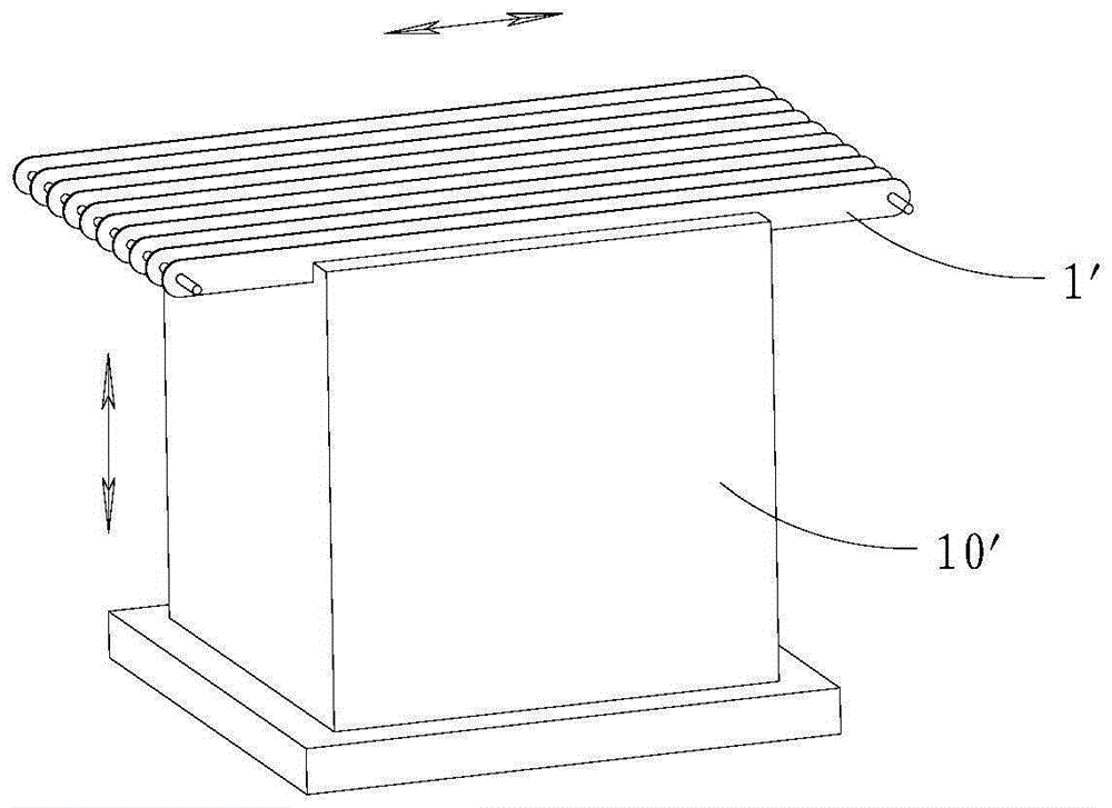
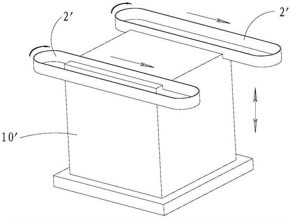
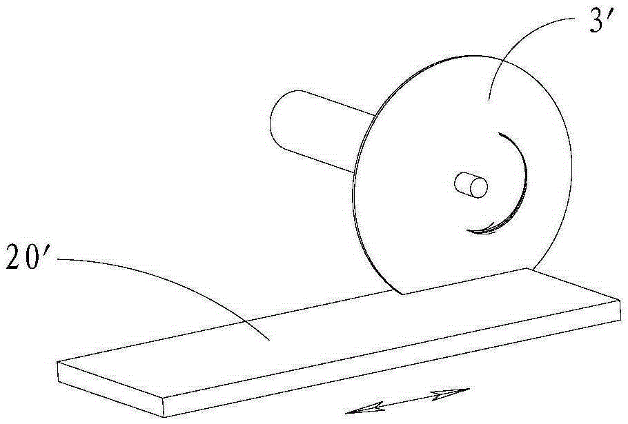
technical field [0001] The invention relates to a swing type marble multi-wire cutting machine. Background technique [0002] At present, in the building decoration industry, especially in the decoration of high-end villas, luxury hotels and other places, marble is used more and more. In addition to the ground, it can also be used for interior and exterior walls and ceilings. After decoration, it is as beautiful as jade and noble. elegant. In the traditional marble cutting process, the main method is to cut large pieces of marble into large pieces, and then cut the large pieces into small pieces for decoration. [0003] When cutting large pieces, it is generally cut with a knife saw or a band saw. When cutting with a saw, if figure 1 As shown, the saw 1' reciprocates, and the marble 10' rises slowly. The saw blade is usually thicker, usually 3-5 mm. This cutting method not only has slow cutting speed, thick marble slices after cutting, and low cutting efficiency. It wil...

Claims


Application Information

Patent Timeline
Patent Type & Authority Patents(China)
IPC IPC(8): B28D1/22B28D7/00
CPCB28D1/22B28D7/00
Inventor 方海波李子法
Owner SUZHOU SILICON PEAK SOLAR TECH
Learn More