Novel rotating base

A rotating base, a new type of technology, applied in the direction of conveyors, bearing components, rigid supports of bearing components, etc., can solve the problems of poor sealing performance, easy failure, and inability to rotate, etc., to achieve good sealing performance, good centering effect, and use long life effect

Inactive Publication Date: 2015-05-13
天津三岛输送机械有限公司
View PDF14 Cites 2 Cited by
  • Summary
  • Abstract
  • Description
  • Claims
  • Application Information

AI Technical Summary

Problems solved by technology

The disadvantages of this structure are: 1. The lithium-based No. 2 lubricating grease in the lubricating chamber 5 between the shaft 1 and the base 2 will gradually lose over time and reduce the lubrication effect, resulting in inflexible rotation or even inability to rotate; 2. The shaft 1. The retaining ring 3 and gasket 4 installed at the bottom of 1 can bear limited force. For example, when the material transported by the belt conveyor has a large impact, it is easy to fail and cause falling off; 3. The sealing performance between the base and the upper beam is poor, and the content of the lubricating chamber Easy to enter impurities and affect the rotation
The disadvantages of this structure are: 1. There is no bearing between the lower end of the center shaft and the base, which will cause inflexible rotation; 2. The sealing performance between the base and the upper beam is poor, and impurities are easy to enter, which affects the rotation
The disadvantages of this structure are: 1. The sealing performance of the base and the upper beam is poor, and impurities are easy to enter and affect the rotation; 2. Neither the one-way ball bearing nor the deep groove ball bearing can withstand large axial loads. When a large impact occurs, the bearing is easily damaged, which affects the service life

Method used


Image

  • Novel rotating base
  • Novel rotating base

Examples


Embodiment Construction

[0012] The present invention will be described in detail below in conjunction with the accompanying drawings and specific embodiments.

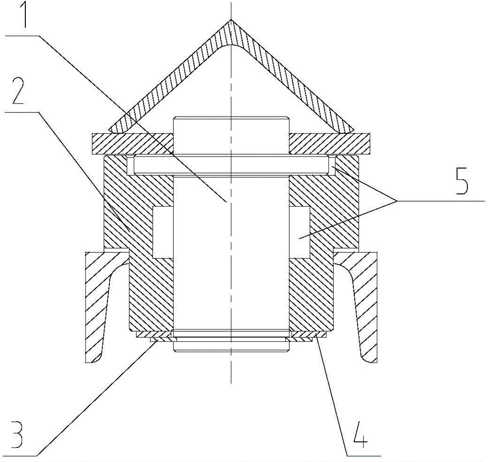
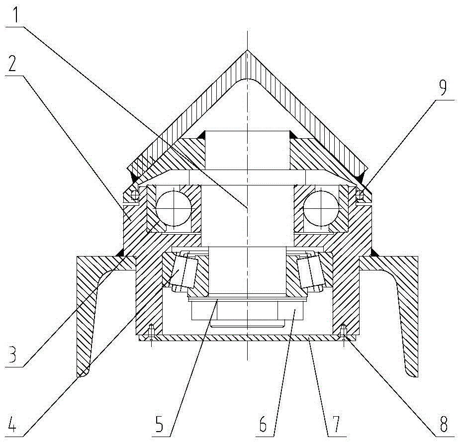
[0013] Such as figure 2 A new type of rotating base of the present invention is shown, which includes a shaft 1 welded to the upper beam of the self-aligning idler and a base 2 welded to the lower beam of the self-aligning idler. Angular contact bearings 3 and tapered roller bearings 4 are respectively installed at intervals between 2, the upper part of the base is nested in the lower part of the opening of the upper beam, and an O-ring is installed between the base and the nesting part of the upper beam 9. A washer 5 is sleeved on the shaft 1 at the lower end surface of the tapered roller bearing 4, and the washer 5 is pressed against the lower end surface of the tapered roller bearing 4 through a nut 6, and the bottom surface of the base is connected with a ( The fixing part can be bolt 8) base end cover 7.

[0014] The installation meth...


PUM


Abstract

The invention discloses a novel rotating base which comprises a shaft and a base. The shaft is connected with an upper cross beam of an alignment carrier roller in a welded mode, the base is connected with a lower cross beam of the alignment carrier roller in a welded mode, an angular contact bearing and a conical roller bearing are arranged between the shaft and the base in a vertically spaced mode, the upper portion of the base is nested in the lower portion of an opening hole in the upper cross beam, an O-shaped seal ring is arranged between the base and the nesting position of the upper cross beam, the part, on the lower end face of the conical roller bearing, of the shaft is sleeved with a gasket, the gasket is tightly pressed to the lower end face of the conical roller bearing through a nut, and a base end cover is connected to the bottom face of the base through fixing parts. The novel rotating base has the advantages that the angular contact bearing and the conical roller bearing are arranged between the shaft and the base, so that the shaft and the base are rotated flexibly; the O-shaped seal ring is arranged between the base and the upper cross beam, the seal performance is good, the alignment effect is good, and the service life is long.

Description

technical field [0001] The invention relates to a rotating base structure. Background technique [0002] Currently, if figure 1 Shown is a known rotating base for self-aligning rollers of belt conveyors, the structure is; first, the shaft 1 and the upper beam of the self-aligning roller are welded, and then the base 2 is welded to the lower beam of the self-aligning roller, Fill the lubricating cavity between the shaft 1 and the base 2 with lithium-based No. 2 grease, and finally install the retaining ring 3 and the washer 4 at the bottom of the shaft 1 to fix them. The disadvantages of this structure are: 1. The lithium-based No. 2 lubricating grease in the lubricating chamber 5 between the shaft 1 and the base 2 will gradually lose over time and reduce the lubrication effect, resulting in inflexible rotation or even inability to rotate; 2. The shaft 1. The retaining ring 3 and gasket 4 installed at the bottom of 1 can bear limited force. For example, when the material tr...

Claims


Application Information

Patent Timeline
Patent Type & Authority Applications(China)
IPC IPC(8): B65G39/09B65G39/16B65G15/64F16C35/10
CPCB65G39/09B65G39/16
Inventor 刘志伟王紫阳吉佳佳白洪普王春龙
Owner 天津三岛输送机械有限公司
Why Eureka
Try Eureka