Loose fiber dyeing machine with rotatable fiber cage

A fiber cage and rotating technology, which is applied in spraying/spraying textile material processing, textile material carrier processing, textile material container processing, etc., can solve the problem of high replacement cost of fiber cage, easy extrusion damage of cylinder body, and increased maintenance cost and other problems, to achieve the effect of improving service life, reducing maintenance costs, and facilitating maintenance and repair

Inactive Publication Date: 2015-05-13
响水县嘉亿纺织有限公司
View PDF4 Cites 11 Cited by
  • Summary
  • Abstract
  • Description
  • Claims
  • Application Information

AI Technical Summary

Problems solved by technology

[0002] In the existing loose fiber dyeing machine, the fiber cage is hoisted into the dye vat, and there is no buffer device at the bottom of the dye vat, so that when the fiber cage is placed into the dye vat, it will collide with the dye vat, causing the dye vat to be damaged. At the same time, the existing There is a cylinder inside the fiber cage to ensure that the nozzle can be inserted into the cylinder for spraying, and the fiber material will not block the middle of the fiber cage. The cylinder is easy to be squeezed and damaged. After damage, the fiber needs to be removed Cage replacement and fiber cage replacement costs are high. At the same time, most of the existing loose fiber dyeing machines use circulating pumps to recycle dyes. Cleaning and maintenance are required, increasing maintenance costs
[0003] Moreover, the existing fiber cages generally do not move or rotate after they are put in, so that the dyes can only be dyed through the spray holes, and the effect is limited.

Method used


Image

  • Loose fiber dyeing machine with rotatable fiber cage
  • Loose fiber dyeing machine with rotatable fiber cage

Examples


Embodiment Construction

[0021] The present invention will be described in detail below in conjunction with accompanying drawings and specific preferred embodiments, so that the advantages and features of the present invention can be more easily understood by those skilled in the art. range is limited.

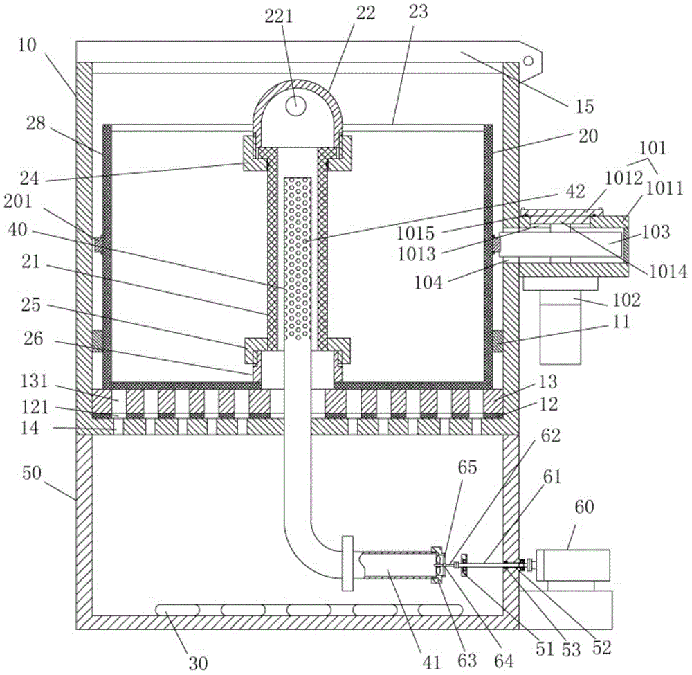
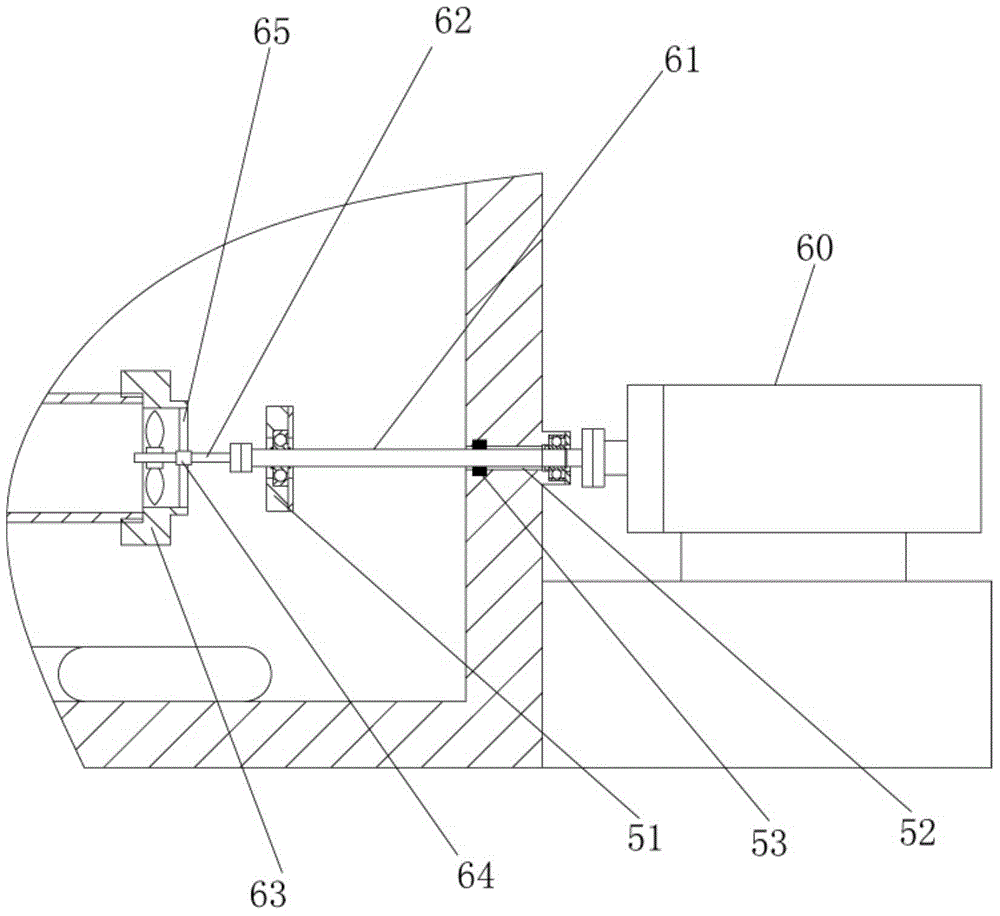
[0022] Examples, see e.g. Figures 1 to 2 Shown, a kind of fiber cage rotatable loose fiber dyeing machine, comprises dye vat 10, fiber cage 20, heating coil 30 and center spray pipe 40, the bottom of described dye vat 10 is fixed with dye tank 50, and dye tank 50 is fixed with The heating coil 30 and the outer wall of the dye tank 50 are fixed with a driving motor 60, the output shaft of the driving motor 60 is connected with an intermediate rotating shaft 61 through a coupling, the intermediate rotating shaft 61 extends into the dye tank 50, and the intermediate rotating shaft 61 passes through the bearing Fixed on the dye tank 50, the other end of the intermediate rotating shaft 61 is connected wi...


PUM


Abstract

The invention discloses a loose fiber dyeing machine with a rotatable fiber cage. The loose fiber dyeing machine comprises a dyeing vat, the fiber cage, a heating coil and a central spray pipe, wherein a dye tank is fixed at the bottom of the dyeing vat; the heating coil is fixed inside the dye tank; a driving motor is fixed on the outer wall of the dye tank; the output shaft of the driving motor is connected with a central rotating shaft through a coupling; a cushion pad is fixed on a bottom plate of the dyeing vat; a wear-resistant lubricating block is fixed on the cushion pad; the bottom of the fiber cage is pressed against the wear-resistant lubricating block; a rotating gear ring is fixed on the outer wall of the fiber cage; a gear shell is arranged on the outer wall of the dyeing vat; a rotating motor is fixed at the bottom of the gear shell; a driving gear is fixed on the output shaft of the rotating motor; the driving gear is meshed with a rotating gear ring. The dyeing vat of the loose fiber dyeing machine has a cushioning mechanism, so that when the fiber cage is hung therein, direct collision is reduced and the service life is prolonged; the fiber cage is rotatable, so that the loose fiber dyeing machine is more uniform in dyeing.

Description

Technical field: [0001] The invention relates to the technical field of textile printing and dyeing equipment, in particular to a fiber cage rotatable loose fiber dyeing machine. Background technique: [0002] In the existing loose fiber dyeing machine, the fiber cage is hoisted into the dye vat, and there is no buffer device at the bottom of the dye vat, so that when the fiber cage is placed into the dye vat, it will collide with the dye vat, causing the dye vat to be damaged. At the same time, the existing There is a cylinder inside the fiber cage to ensure that the nozzle can be inserted into the cylinder for spraying, and the fiber material will not block the middle of the fiber cage. The cylinder is easy to be squeezed and damaged. After damage, the fiber needs to be removed Cage replacement and fiber cage replacement costs are high. At the same time, most of the existing loose fiber dyeing machines use circulating pumps to recycle dyes. Cleaning and maintenance are re...

Claims


Application Information

Patent Timeline
IPC IPC(8): D06B1/02D06B23/04D06B23/14D06B23/20
CPCD06B1/02D06B23/04D06B23/14D06B23/20
Inventor 方永强
Owner 响水县嘉亿纺织有限公司
Why Eureka
Try Eureka