Torque converters for motor vehicles

A technology for hydraulic torque converters and motor vehicles, applied in the field of hydraulic torque converters, can solve problems such as damage, noise of starting components, etc., and achieve the effect of reducing the effect

Active Publication Date: 2019-12-03
SCHAEFFLER TECH AG & CO KG
View PDF7 Cites 0 Cited by
  • Summary
  • Abstract
  • Description
  • Claims
  • Application Information

AI Technical Summary

Problems solved by technology

Sudden starting movements can occur here, which lead to noise generation within the starting element
Sensitive components, especially the pendulum mass of the centrifugal pendulum, can also be damaged in the event of too strong a shake (Ruck)

Method used


Image

  • Torque converters for motor vehicles
  • Torque converters for motor vehicles
  • Torque converters for motor vehicles

Examples


Embodiment Construction

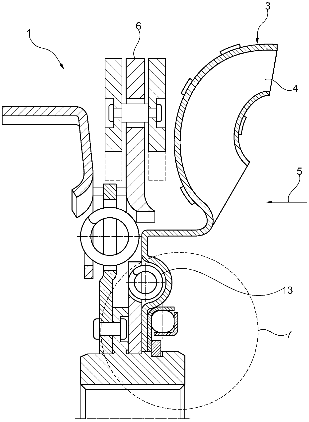
[0038] exist figure 1 shows a torque converter 1 with a turbine 3 , here only the turbine blades 4 of which can be seen, which can be driven by a hydraulic fluid 5 . In this case, the anti-vibration device 6 , here a centrifugal pendulum, is connected via an elastic connecting element 7 . In this case, the elastic connecting element 7 is formed by a bow spring 13 which also has dissipative properties at the same time.

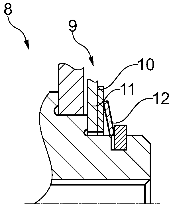
[0039] exist figure 2 A section of a hydraulic torque converter 1 is shown in , that is, a dissipating element 8, which is arranged as figure 1 In the position of the elastic connecting element 7 . In this case, the dissipating element 8 is formed by a friction-fit connection 9 which is produced by a first friction surface 10 and a second friction surface 11 which are pressed against each other by means of a disc spring 12 pressure.

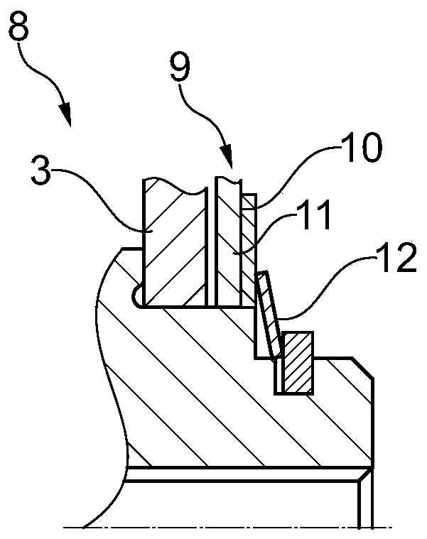
[0040] exist image 3 shown in figure 2 A similar arrangement as in , wherein here the first friction surface 10 and th...


PUM


Abstract

Hydrodynamic torque converter for a motor vehicle, comprising at least the following components: a turbine with turbine blades for a hydrodynamic fluid; an anti-vibration device which includes at least one centrifugal pendulum, for emptying vibrations; an elastic connecting element between the turbine and the anti-vibration device, which transmit a rotary motion between the turbine and the anti-vibration device. Also, the invention relates to a hydrodynamic torque converter for a motor vehicle, comprising at least the following components: a turbine with turbine blades for a hydrodynamic fluid; an anti-vibration device for damping and / or emptying vibrations; a dissipation element, which connects the turbine with the anti-vibration device and which transmits a rotational movement between the turbine and the anti-vibration device. With the hydrodynamic torque converter proposed here, it is possible to achieve noise reduction and preservation of elements of an anti-vibration device in a small space.

Description

technical field [0001] The invention relates to a hydrodynamic torque converter for a motor vehicle, in particular a starter element, which has a centrifugal pendulum. Background technique [0002] Hydrodynamic starting elements are known from the prior art with which a motor vehicle can be brought into a driving motion from a standstill. In this case, a rotational movement is generated by the turbine blades by the liquid being pumped. Sudden starting movements can occur here, which lead to noise generation within the starting element. Sensitive components, especially the pendulum mass of the centrifugal pendulum, can also be damaged in the event of too strong a jolt. Contents of the invention [0003] Proceeding from this, the object of the invention is to at least partially overcome the disadvantages known from the prior art. This task is solved by the features of the independent claims. Advantageous refinements are the subject matter of the subclaims. [0004] The ...

Claims


Application Information

Patent Timeline
Patent Type & Authority Patents(China)
IPC IPC(8): F16H41/04F16H41/24F16F15/14
CPCF16F15/145F16H41/04F16H41/24F16H45/02F16H2045/0263F16H2045/0284
Inventor S·马延沙因
Owner SCHAEFFLER TECH AG & CO KG
Why Eureka
Try Eureka