Microfluidic chip-based immunoaggregation detection method, chip and system
A microfluidic chip and detection method technology, applied in the field of immune detection, can solve the problems of low sensitivity and inability to meet the detection requirements of low-concentration antigens, and achieve the effects of increasing the reaction rate, reducing the amount of samples, and reducing the detection limit
- Summary
- Abstract
- Description
- Claims
- Application Information
AI Technical Summary
Problems solved by technology
Method used
Image
Examples
Embodiment 1
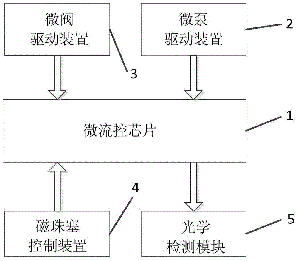
[0081] The immunoaggregation detection system in this embodiment has a structure such as figure 2 , Figure 5 , Figure 7 , Figure 9 , Figure 10 , Figure 11 and Figure 13 As shown, it consists of a microfluidic chip, a micropump driving device, a microvalve driving device, a magnetic bead plug control device and an optical detection module.
[0082] In this example, if Figure 13 The fabrication process of the immunoaggregation detection system shown is as follows:
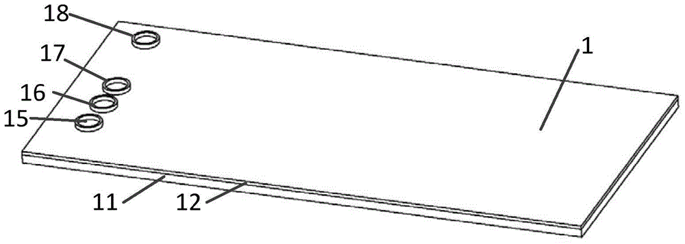
[0083] A01, make microchannels on the plexiglass substrate 11, then bond the substrate 11 and the flexible polymer layer 12 to form a microchannel system;
[0084] A02, punching holes on the flexible polymer layer 12, making a buffer solution inlet 15, a sample inlet 16, a magnetic bead inlet 17, and a waste liquid outlet 18 to form a microfluidic chip 1;
[0085] A03. Arrange the micropump drive mechanism 2 above the micropump area 13 of the microfluidic chip 1, and align the steel ball 24 with the a...
Embodiment 2
[0103] The microfluidic chip-based immunoaggregation detection system in this embodiment has a structure such as figure 2 , Figure 5 , Figure 7 , Figure 9 , Figure 10 , Figure 11 and Figure 13 shown.
[0104] The difference between this embodiment and Embodiment 1 is that: the lower surface of the flexible polymer layer 12 is provided with microchannels; the flexible polymer 12 and the substrate 11 are bonded to form a microchannel system. Other structures are the same as those in Embodiment 1, and will not be repeated here.
Embodiment 3
[0106] The microfluidic chip-based immunoaggregation detection system in this embodiment has a structure such as figure 2 , Figure 5 , Figure 7 , Figure 9 , Figure 10 , Figure 11 and Figure 13 shown.
[0107] The difference between this embodiment and Embodiment 1 is: the moving magnet 41 swings around the shaft 45, and the moving magnet 42 swings around the shaft 46; the speed at which the magnet 41 swings around the shaft 45 is equal to the frequency at which the magnet 42 swings around the shaft 46, which is 0.1 Hz to 100Hz; when the magnet 41 is facing the microfluidic chip, the magnet 42 swings at a position not facing the microfluidic chip; when the magnet 42 is facing the microfluidic chip, the magnet 41 swings at a position not facing the microfluidic chip Location. Other structures are the same as those in Embodiment 1, and will not be repeated here.
PUM
 Abstract
Description
Claims
Application Information
 - R&D
- Intellectual Property
- Life Sciences
- Materials
- Tech Scout
- Unparalleled Data Quality
- Higher Quality Content
- 60% Fewer Hallucinations
Browse by: Latest US Patents, China's latest patents, Technical Efficacy Thesaurus, Application Domain, Technology Topic, Popular Technical Reports.
© 2025 PatSnap. All rights reserved.Legal|Privacy policy|Modern Slavery Act Transparency Statement|Sitemap|About US| Contact US: help@patsnap.com


