Immune agglomeration detection method, chip and system based on micro-fluidic chip

A technology of a microfluidic chip and a detection method, which is applied in the field of immunoassay, can solve the problems of inability to meet the needs of low-concentration antigen detection and low sensitivity, and achieve the effects of reducing the amount of samples, increasing the reaction rate, and increasing the concentration.

Inactive Publication Date: 2015-05-13
TSINGHUA UNIV
View PDF4 Cites 20 Cited by
  • Summary
  • Abstract
  • Description
  • Claims
  • Application Information

AI Technical Summary

Problems solved by technology

Although the immunoaggregation detection is easy to operate, the sensitivity of the method of directly detecting the change of the transmitted light or scattered light intensity of the reaction system is relatively low, which cannot meet the detection requirements of low-concentration antigens

Method used


Image

  • Immune agglomeration detection method, chip and system based on micro-fluidic chip
  • Immune agglomeration detection method, chip and system based on micro-fluidic chip
  • Immune agglomeration detection method, chip and system based on micro-fluidic chip

Examples


Embodiment 1

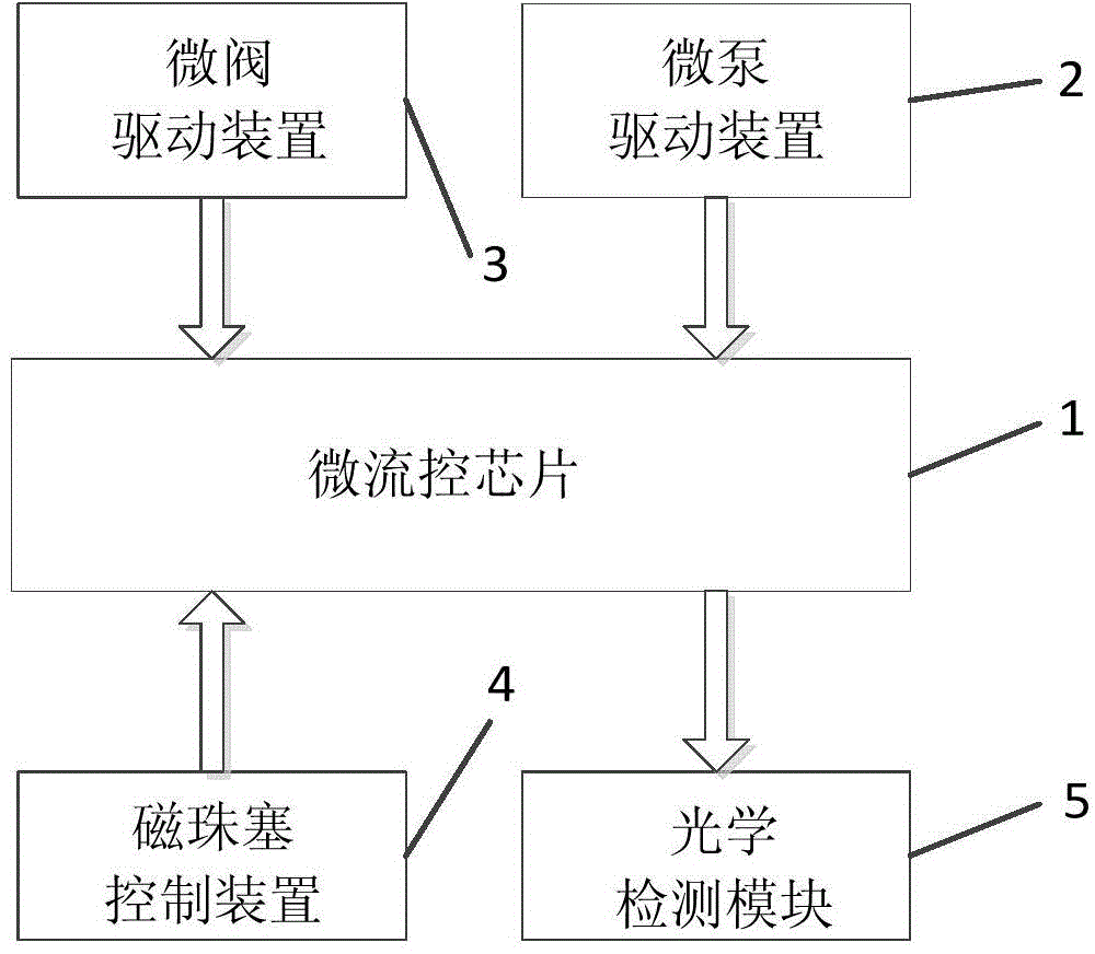
[0081] The immunoaggregation detection system in this embodiment has a structure such as figure 2 , Figure 5 , Figure 7 , Figure 9 , Figure 10 , Figure 11 and Figure 13 As shown, it consists of a microfluidic chip, a micropump driving device, a microvalve driving device, a magnetic bead plug control device and an optical detection module.

[0082] In this example, if Figure 13 The fabrication process of the immunoaggregation detection system shown is as follows:

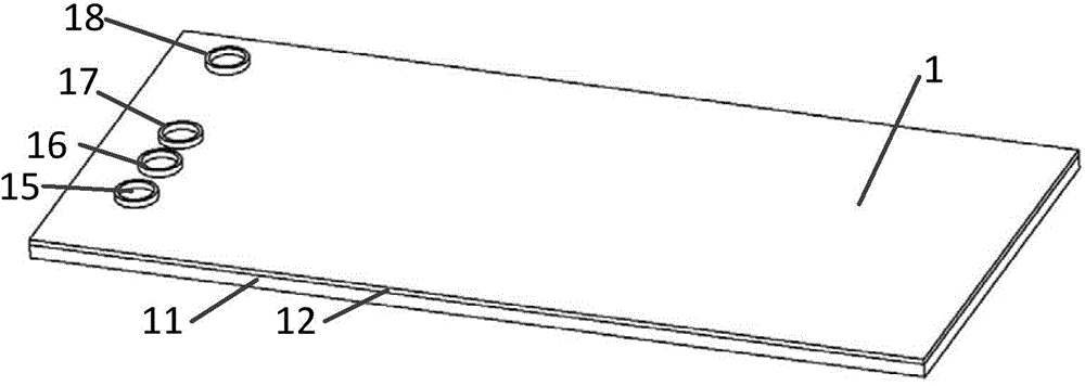
[0083] A01, make microchannels on the plexiglass substrate 11, then bond the substrate 11 and the flexible polymer layer 12 to form a microchannel system;

[0084] A02, punching holes on the flexible polymer layer 12, making a buffer solution inlet 15, a sample inlet 16, a magnetic bead inlet 17, and a waste liquid outlet 18 to form a microfluidic chip 1;

[0085] A03. Arrange the micropump drive mechanism 2 above the micropump area 13 of the microfluidic chip 1, and align the steel ball 24 with the a...

Embodiment 2

[0103] The microfluidic chip-based immunoaggregation detection system in this embodiment has a structure such as figure 2 , Figure 5 , Figure 7 , Figure 9 , Figure 10 , Figure 11 and Figure 13 shown.

[0104] The difference between this embodiment and Embodiment 1 is that: the lower surface of the flexible polymer layer 12 is provided with microchannels; the flexible polymer 12 and the substrate 11 are bonded to form a microchannel system. Other structures are the same as those in Embodiment 1, and will not be repeated here.

Embodiment 3

[0106] The microfluidic chip-based immunoaggregation detection system in this embodiment has a structure such as figure 2 , Figure 5 , Figure 7 , Figure 9 , Figure 10 , Figure 11 and Figure 13 shown.

[0107] The difference between this embodiment and Embodiment 1 is: the moving magnet 41 swings around the shaft 45, and the moving magnet 42 swings around the shaft 46; the speed at which the magnet 41 swings around the shaft 45 is equal to the frequency at which the magnet 42 swings around the shaft 46, which is 0.1 Hz to 100Hz; when the magnet 41 is facing the microfluidic chip, the magnet 42 swings at a position not facing the microfluidic chip; when the magnet 42 is facing the microfluidic chip, the magnet 41 swings at a position not facing the microfluidic chip Location. Other structures are the same as those in Embodiment 1, and will not be repeated here.


PUM


Abstract

The invention provides an immune agglomeration detection method based on a micro-fluidic chip. The immune agglomeration detection method comprises the following steps: dynamically enriching immunomagnetic beads by virtue of a micro-fluidic chip by controlling a specific region of a magnetic field in a chip micro-channel to form a magnetic bead plug; controlling a sample liquid to flow through the magnetic bead plug in cycle and capturing antigen in the sample liquid by the immunomagnetic beads; combining the antigen captured by the immunomagnetic beads with another magnetic beads to form two or more agglomerations of the magnetic beads; and counting the quantity of single magnetic beads and the agglomerated magnetic beads by detecting scattered light signals of the magnetic beads to obtain the concentration of the antigen in the sample. The invention provides the micro-fluidic chip. The invention further provides an immune agglomeration detection system based on the micro-fluidic chip. The detection system comprises the micro-fluidic chip, a micro-pump drive device, a micro-valve drive device, a magnetic bead plug control device and an optical detection module. According to the immune agglomeration detection method and system, achievement of a miniature immune detection instrument is facilitated; the detection limit is reduced; and detection of low-concentration antigen is achieved.

Description

technical field [0001] The invention relates to the technical field of immune detection, in particular to a microfluidic chip-based immune aggregation detection method, chip and system. Background technique [0002] In recent years, people have paid more and more attention to food safety, environmental sanitation, and on-site rapid disease diagnosis. It is increasingly important to develop a portable, real-time, and easy-to-operate detection system. Among many detection methods, immunoassay has attracted much attention due to its specificity of antigen-antibody binding. The most commonly used immunoassay strategy is enzyme-linked immunosorbent assay (ELISA). The main methods are: locking the antigen through the sandwich method, and realizing signal amplification and detection with the help of antibody labeling. The standard ELISA method is complicated to operate. When performing immunoassays based on microfluidic chips, it generally requires multi-step operations such as im...

Claims


Application Information

Patent Timeline
Patent Type & Authority Applications(China)
IPC IPC(8): G01N33/553B01L3/00
CPCB01L3/00G01N33/553
Inventor 叶雄英马增帅成一诺谢帅张帅
Owner TSINGHUA UNIV
Why Eureka
Try Eureka