
Electrochromic mirror

An electrochromic, electrochromic layer technology, applied in the direction of optics, instruments, optical observation devices, etc., to achieve the effect of ensuring insulation

Inactive Publication Date: 2015-05-13
HONDA LOCK MFG CO LTD
View PDF7 Cites 2 Cited by
  • Summary
  • Abstract
  • Description
  • Claims
  • Application Information

AI Technical Summary

Problems solved by technology

However, when the rectangular transparent conductive film, EC layer, and reflective film-cum-electrode film are shifted along the short side direction of the rectangle when viewed from the normal direction of the glass substrate, although the long sides of each layer are shifted by The state is configured, but the short sides of each layer are configured in a partially overlapping state

Method used


Image

  • Electrochromic mirror
  • Electrochromic mirror
  • Electrochromic mirror

Examples


no. 1 approach

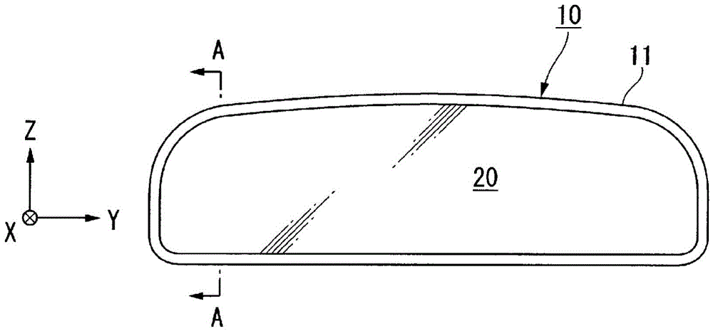
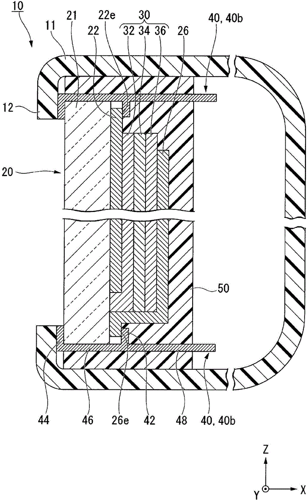
[0036] figure 2 It is a front view of the EC mirror 10 of the first embodiment. image 3 is an explanatory diagram of the EC mirror 10 of the first embodiment, and is figure 2 A sectional view at line A-A of . Such as image 3 As shown, the EC mirror 10 includes an EC mirror body 20, a power supply terminal 40 for supplying power to the EC mirror body 20, an ion insulating material 50 covering the EC mirror body 20, and a mirror holder 11 supporting the EC mirror body 20. . The EC mirror main body 20 is formed by sequentially laminating a transparent electrode film 22 , an EC layer 30 that develops color by voltage application, and a reflective electrode film 26 on the +X surface (first surface) of a transparent substrate 21 .

[0037] The transparent substrate 21 is formed of a material (glass, etc.) having visible light permeability. The transparent electrode film 22 is formed of a material (ITO, etc.) having visible light permeability and conductivity to a thickness ...

no. 2 approach

[0083] Figure 11 is an explanatory diagram of the EC mirror 210 of the second embodiment, and is the same as figure 2 A cross-sectional view of a portion corresponding to line A-A. image 3 The shown EC mirror 10 of the first embodiment has the projecting portion 22e of the transparent electrode film 22 formed on the +Z side of the EC layer 30, and the projecting portion 22e of the reflective electrode film 26 is formed on the −Z side of the EC layer 30. Section 26e. in comparison, Figure 11 The EC of the second embodiment shown differs from the first embodiment in that the reflecting mirror 210 includes the entirety of the EC layer 30 inside the transparent electrode film 22 and includes the entirety of the reflective electrode film 26 inside the EC layer 30 . In addition, the detailed description of the part which has the same structure as 1st Embodiment is abbreviate|omitted.

[0084] Such as Figure 11 As shown, in the EC mirror 210 , the transparent electrode film 2...


PUM


Abstract

Provided is an electrochromic (EC) mirror such that insulation between electrodes can be ensured. On a +X surface of a transparent substrate (21), a transparent electrode film (22), an EC layer (30) that produces a color when a voltage is applied, and a reflective electrode film (26) are sequentially layered. When viewed from the +X direction, a protruding part (22e) of the transparent electrode film (22) is formed at the +Z side of the EC layer (30), and a protruding part (26e) of the reflective electrode film (26) is formed at the -Z side of the EC layer (30). When viewed from the +X direction, the entirety of the overlapping area (24) where the transparent electrode film (22) and the reflective electrode film (26) overlap is contained on the inside of the EC layer (30).

Description

technical field [0001] The present invention relates to, for example, an automatic anti-glare mirror used in a vehicle's interior rearview mirror and door mirror, and particularly relates to an electrochromic mirror that achieves an anti-glare effect by coloring the mirror through a redox reaction based on an applied voltage Mirror (electrochromic mirror). Background technique [0002] When driving a vehicle at night, the light of the headlights of the following vehicles is reflected at the interior rearview mirror and the door rearview mirror, which sometimes feels dazzling. Therefore, an EC mirror having an electrochromic (hereinafter, sometimes abbreviated as "EC") layer that develops color upon application of a voltage has been developed. The EC mirror applies a voltage to the EC layer to develop color when the surroundings are dark and strong light is irradiated from the following vehicle. Thereby, reflection of light from a following vehicle can be suppressed, and gl...

Claims


Application Information

Patent Timeline
IPC IPC(8): G02F1/155G02F1/15G02F1/153
CPCB60R1/088G02F1/133553G02F1/155G02F1/157G02F2001/1555
Inventor 久木田知之
Owner HONDA LOCK MFG CO LTD
Learn More