
Rotary conductive joint device and method of using same

A technology of conductive joints and conductive cores, applied in charging stations, electric vehicles, transportation and packaging, etc., can solve the problems of cable and bow frame coordination, unreasonable appearance, large bending radius, easy wear, etc. Current limitation and bending service life, ensuring firmness and conductivity, and solving the effect of safety

Pending Publication Date: 2020-01-17
北京维通利电气有限公司
View PDF0 Cites 0 Cited by
  • Summary
  • Abstract
  • Description
  • Claims
  • Application Information

AI Technical Summary

Problems solved by technology

[0005] When the charging plate moves up and down repeatedly, the high-current cable connected to the charging plate also needs to move repeatedly at the same time and bend continuously. Therefore, the cable is constantly bent, which is easy to wear and has a low service life.
In addition, in order to make the cable meet the current-carrying requirements, it is necessary to use a thick-gauge cable. The cable is bulky and has a large bending radius, which makes the charging bow unable to flexibly lift and charge.
In addition, the coordination and appearance of the cable and the bow frame are very unreasonable

Method used


Image

  • Rotary conductive joint device and method of using same
  • Rotary conductive joint device and method of using same
  • Rotary conductive joint device and method of using same

Examples


Embodiment Construction

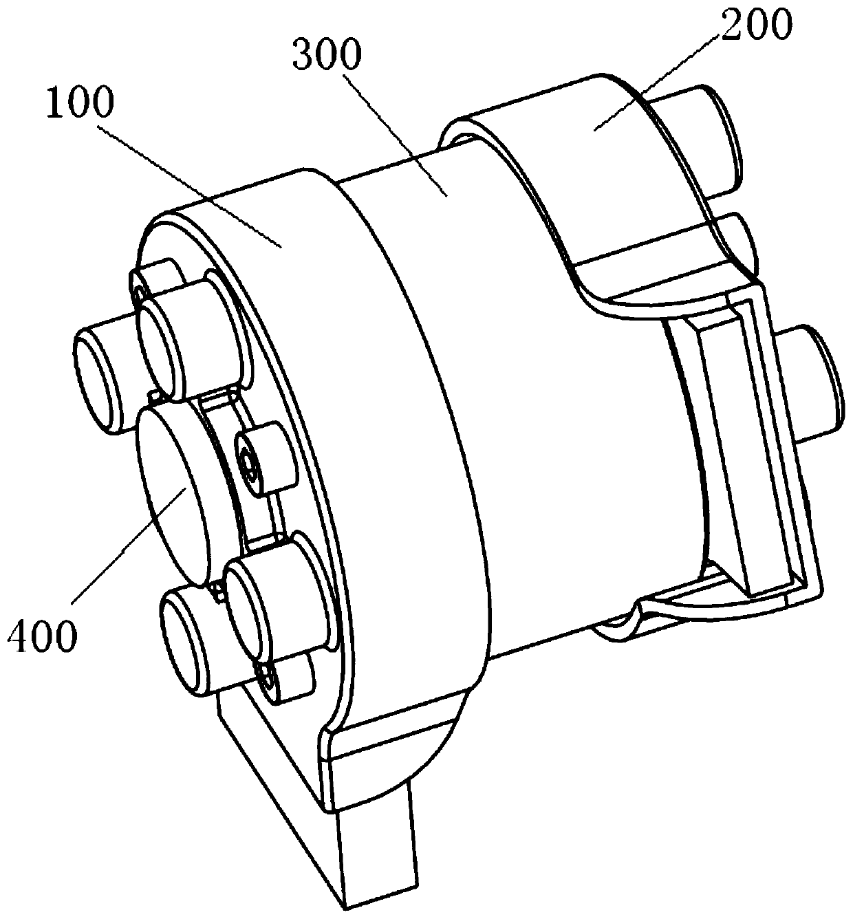
[0035] In order to make the technical problems, technical solutions and beneficial effects solved by the present invention clearer, the present invention will be further described in detail below in conjunction with the accompanying drawings and embodiments. It should be understood that the specific embodiments described here are only used to explain the present invention, not to limit the present invention.

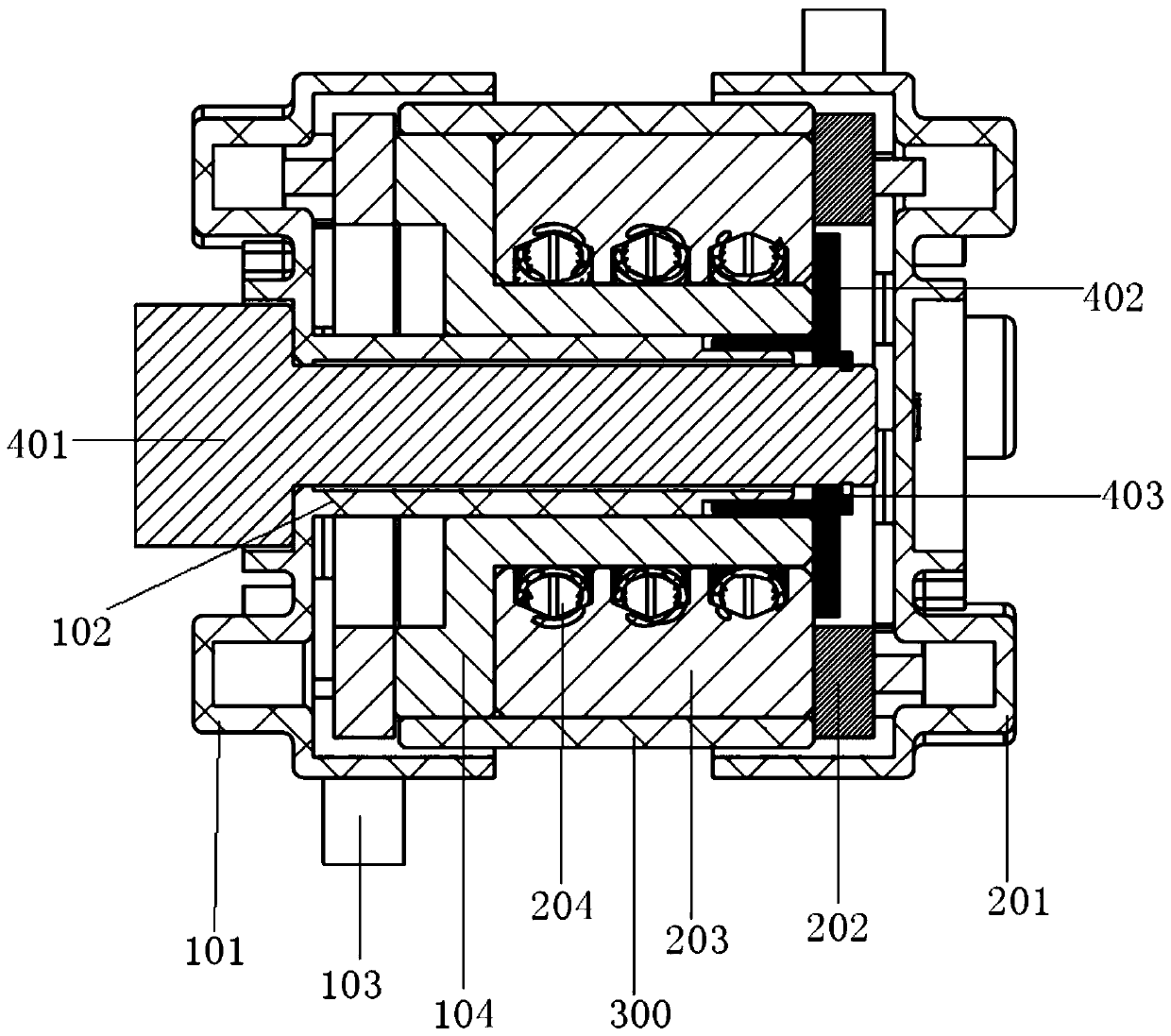
[0036] The invention provides a rotating conductive joint device, which has the advantages of firm rotation, electrical conductivity and safety. Conductive current transmission can be carried out in the process of free rotation, and the two rotating parts that are flexibly connected are positioned by the clamp spring, which can ensure the stable contact between the conductive mandrel and the conductive ring sleeve in flexible contact, and the selection of appropriate grease ensures the conductive joints service life. It not only solves the safety of conduction and the a...


PUM


Abstract

The invention provides a rotary conductive joint device and a using method thereof. The rotary conductive joint device comprises a first rotary conductive unit, a second rotary conductive unit, an insulating sheath and a connecting limiting unit. The first rotary conductive unit comprises a first insulating protective cover, an insulating shaft, a first conductive connecting bar and a conductive mandrel; and the second rotary conductive unit comprises a second insulating protective cover, a second conductive connecting bar, a conductive loop and a conductive spring. According to the rotary conductive joint device and the using method thereof, the functions of rotation and electric conduction are achieved, the firmness and the electric conductivity of the structure can be guaranteed, and the insulativity and the safety during work can also be guaranteed. The rotary conductive joint device can be applied to the field of large-current motion transmission in the free lifting or moving process of an electric vehicle charging device, the safety of electric conduction and the appearance attractiveness of an electric conduction device are achieved, the current-carrying limitation of cableelectric conduction is avoided, and the bending service life is prolonged.

Description

technical field [0001] The invention belongs to the technical field of charging devices for electric vehicles, and in particular relates to a rotating conductive joint device and a using method thereof. Background technique [0002] At present, large vehicles such as electric buses mainly use charging bows for fast charging. Compared with traditional charging piles, the charging time of charging bows can be shortened from the original 3 hours to 15 minutes, which greatly shortens the charging time and makes electric vehicles It takes only 5 minutes for the bus to quickly replenish its power at the first and last stations. Therefore, the charging method of the charging bow is convenient for dispatching urban bus lines, reducing charging time and reducing the investment of public transport vehicles, and its application is becoming more and more extensive. [0003] Charging bow charging breaks through the limit of the maximum output current of a single gun of 250A stipulated b...

Claims


Application Information

Patent Timeline
IPC IPC(8): B60L53/14
CPCB60L53/14Y02T10/70Y02T10/7072Y02T90/14
Inventor 张实丹韩永军刘玉斌
Owner 北京维通利电气有限公司
Learn More