Automatic cervical traction chair structure

A cervical traction chair and automatic technology, applied in medical science, fractures and other directions, can solve the problems of non-adjustable height and no backrest adjustment function, and achieve the effect of improving comfort, further treatment effect, and realizing automatic control.

Active Publication Date: 2015-05-20
XUZHOU COLLEGE OF INDAL TECH
View PDF5 Cites 9 Cited by
  • Summary
  • Abstract
  • Description
  • Claims
  • Application Information

AI Technical Summary

Problems solved by technology

[0004] The invention discloses a structure of an automatic cervical traction chair, and completes the design of the automatic cervical traction chair and part of its structure and size in combination with the research results of human body mechanics and the design principle of a rest-type seat, and overcomes that the existing cervical traction chair does not have backrest adjustment Functionality and disadvantages of non-height adjustment

Method used


Image

  • Automatic cervical traction chair structure
  • Automatic cervical traction chair structure

Examples


Embodiment Construction

[0009] The following are specific embodiments of the present invention, and the present invention will be further described in conjunction with the accompanying drawings.

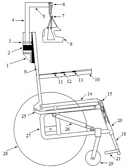
[0010] Such as figure 1 , figure 2 As shown, a kind of automatic cervical spine traction chair structure, comprises seat seat surface 14, the seat back 9 that is connected with seat seat surface 14 and the seat armrest 10 that is arranged on the seat back 9, described seat back 9. A hydraulic cylinder 2 is fixed at the rear by a fixed ring 3. The lower end of the hydraulic cylinder 2 is supported by a support pad 1, and the upper end is connected to a hydraulic cylinder piston rod 4. The upper end of the hydraulic cylinder piston rod 4 is connected to one end of the beam 5. The other end of crossbeam 5 is provided with a pressure sensor 6, and a suspension hook 7 is suspended below the pressure sensor 6, and a helmet-type neck angle controller 8 is connected below the suspension hook 7; 15 is connected w...


PUM


Abstract

An automatic cervical traction chair structure comprises a chair seat surface, a chair backrest connected with the chair seat surface and chair armrests on the chair backrest. A hydraulic cylinder is fixed behind the chair backrest through a fixing round ring, the lower end of the hydraulic cylinder is supported by a supporting sizing block, the upper end of the hydraulic cylinder is connected with a hydraulic cylinder piston rod, the upper end of the hydraulic cylinder piston rod is connected with one end of a cross beam, a pressure sensor is arranged at the other end of the cross beam, a lifting hook is suspended on the lower portion of the pressure sensor, and the lower portion of the lifting hook is connected with a helmet type neck angle controller. The end, away from the chair backrest, of the chair seat surface is connected with an outer casing pipe through a screw, a lifting rod is sleeved with the outer casing pipe, and a pedal is arranged at the lower end of the lifting rod. The lower end of the chair backrest is hinged to a backrest connecting rod. A support connected with the chair seat surface is arranged on the lower portion of the chair seat surface, and the backrest connecting rod is hinged to the support through a supporting connecting rod. A small pulley is arranged on the side, close to the pedal, of the support, and a large pulley is arranged on the other side of the support.

Description

technical field [0001] The invention relates to the field of cervical traction device design, in particular to an automatic cervical traction chair structure. Background technique [0002] As one of the main pillars of the human body, the cervical spine is rich in blood vessels and nerve plexuses, which ensure the upload and release of basic life activity information and nutrient delivery. In real life, the incidence of cervical spondylosis is very high, especially the occupational diseases of teachers, computer workers and other people who work at desks for a long time. According to statistics, there are about 50 million to 150 million people suffering from this disease nationwide, and the incidence rate is about 3.8%-17.6%. At present, there are many medical methods for treating cervical spondylosis, which can be roughly divided into surgical therapy and non-surgical therapy. Cervical traction is an important and commonly used effective therapy in non-surgical therapy of ...

Claims


Application Information

Patent Timeline
Patent Type & Authority Applications(China)
IPC IPC(8): A61F5/042
Inventor 周天沛
Owner XUZHOU COLLEGE OF INDAL TECH
Why Eureka
Try Eureka