Air rectification cap deep drawing die with deep drawing beads

An air rectification and deep drawing die technology, applied in the field of mechanical processing and stamping, can solve the problems of uneven wrinkle parts, inability to stretch and form, and wrinkle, etc., and achieve the effects of significant economic benefits, quality assurance, and high technical value.

Inactive Publication Date: 2015-05-20
HARBIN JIANCHENG GRP
View PDF6 Cites 13 Cited by
  • Summary
  • Abstract
  • Description
  • Claims
  • Application Information

AI Technical Summary

Problems solved by technology

[0004] The purpose of the present invention is to provide an air fairing cap drawing die with drawing ribs, so as to solve the problem that three sets of dies cannot be drawn, and the spherical part of the drawing part is either cracked or wrinkled, and the wrinkled parts After the shape correction process, the wrinkled part is still not smooth, and there are still uneven wrinkled creases on the surface, which cannot meet the problem of product design

Method used


Image

  • Air rectification cap deep drawing die with deep drawing beads
  • Air rectification cap deep drawing die with deep drawing beads
  • Air rectification cap deep drawing die with deep drawing beads

Examples


specific Embodiment approach 1

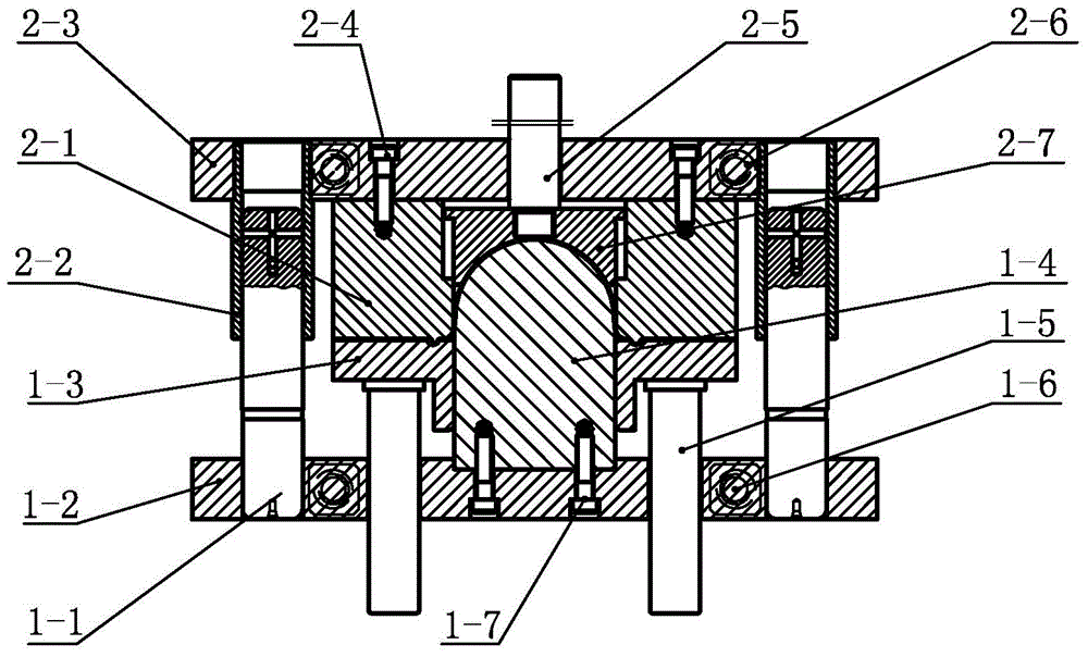
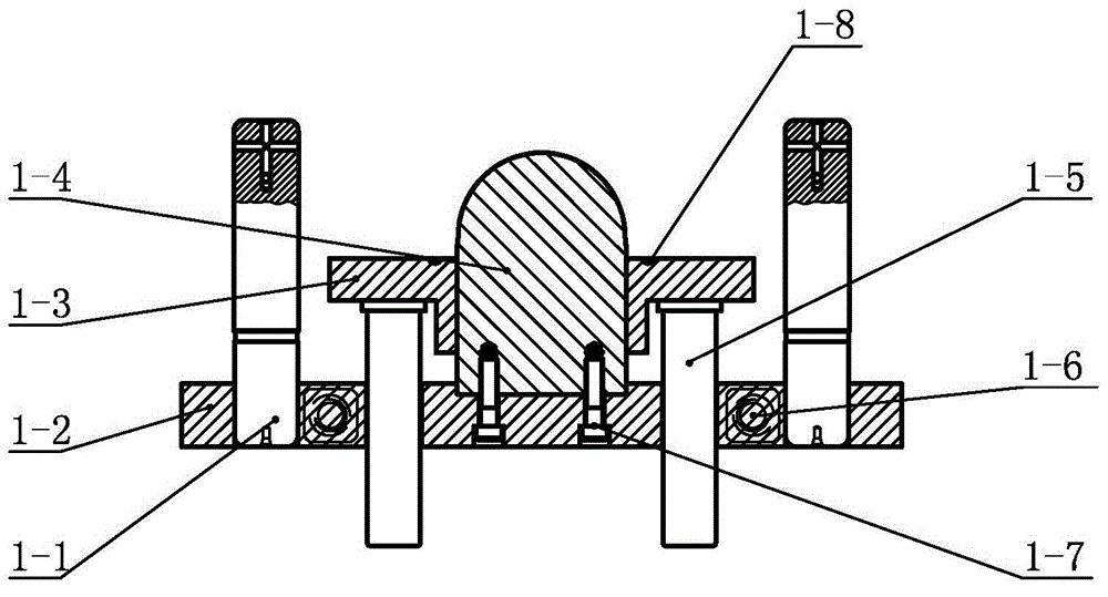
[0011] Specific implementation mode one: combine Figure 1 to Figure 10 Illustrate this embodiment, a kind of air fairing cap drawing mold that has drawing bead of this embodiment, comprises upper mold assembly and lower mold assembly; Said lower mold assembly includes lower mold base 1-2, press Side ring 1-3, punch 1-4, two guide pillars 1-1, four lower die rings 1-6 and at least four blank-holding ejector pins 1-5; Two guide post fixing holes are arranged symmetrically with respect to the vertical center line, the lower ends of the two guide posts 1-1 are fixed in the two guide post fixing holes of the lower mold base 1-2, and the punch 1-4 (through a screw one 1-7) It is connected with the middle part of the upper surface of the lower die base 1-2; the blank holder ring 1-3 is set outside the punch 1-4, and the blank holder ring 1-3 is slidingly matched with the punch 1-4 (binder ring 1-3 can slide up and down along the punch 1-4); the two opposite side walls of the lower ...

specific Embodiment approach 2

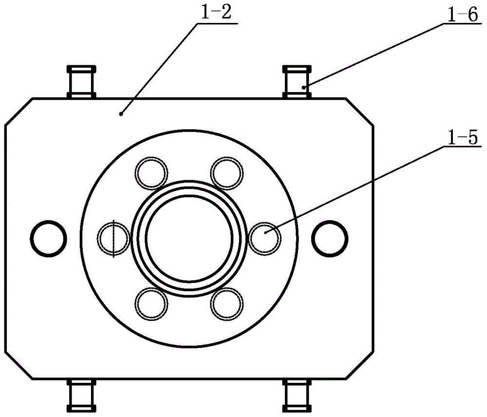
[0013] Specific implementation mode two: combination Figure 1 to Figure 4 Explain that the lower mold base 1-2 described in this embodiment is provided with six ejector pin penetration holes, and the six ejector pin penetration holes are evenly distributed on the same circumference, and the center of the circumference is the same as the lower mold base 1-2. The center is concentric. Good processing stability. The undisclosed technical features in this embodiment are the same as those in the specific embodiment.

[0014] The working principle of the present invention is:

[0015] The guide column 1-1 is fixed on the working table of the equipment along with the lower mold assembly, and the upper mold guide sleeve 2-2 is fixed on the upper slider of the equipment along with the upper mold assembly. After the mold is connected to the equipment, start the equipment Make the upper slider of the equipment drive the upper die assembly to rise to the upper dead point, start the ai...


PUM


Abstract

The invention provides an air rectification cap deep drawing die with deep drawing beads and relates to an air rectification cap deep drawing die. The air rectification cap deep drawing die is used for solving the problems that three sets of dies are used, drawing forming cannot be achieved, a spherical part of a deep drawn part is either ripped or wrinkled, and after a wrinkled part passes through the shaping process, the wrinkled part is not smooth, and wrinkles and folded marks still exist on the surface of the winkled part. Guide pillars are fixed to a lower die seat, and a male die is connected with the lower die seat; an edge pressing ring is arranged on the outer edge of the male die in a sleeving mode; lower die hanging rings are connected with the lower die seat; edge pressing ejecting rods in sliding fit penetrate into ejecting rod penetrating holes of the lower die seat; the edge pressing ejecting rods eject to the lower surface of the edge pressing ring; a female die is connected with an upper die seat; guide sleeves are fixed in guide sleeve fixing holes in the upper die seat; a part ejecting rod penetrates through the upper die seat and is connected with a part ejecting device; the part ejecting device is arranged in a female die counter bore; four upper die hanging rings are connected with the upper die seat, an annular boss is arranged on the lower end face of the female die, and an annular groove is formed in the upper end face of the edge pressing ring. According to the air rectification cap deep drawing die, a press is used for drawing and machining air rectification caps.

Description

technical field [0001] The invention relates to an air fairing cap drawing die, which belongs to the field of mechanical processing and stamping. Background technique [0002] Stamping is a process method of mechanical processing. It uses a press to pressurize a metal blank through a mold to cause plastic deformation to obtain parts of a certain shape, size and performance. It is one of the important processing methods in mechanical manufacturing. . There are many types of parts produced by stamping methods, and their forming methods are also varied. According to the types of forming processes, they can be divided into two categories, one is the separation process, and the other is the forming process. The forming process refers to the plastic deformation of the material without destroying the material, so as to obtain the required shape and size of the workpiece. The forming process includes bending, deep drawing, bulging, flanging, reaming, shrinking, curling, leveling, ...

Claims


Application Information

Patent Timeline
Patent Type & Authority Applications(China)
IPC IPC(8): B21D37/10
CPCB21D37/10B21D22/22B21D37/12
Inventor 许雁冰许连辅
Owner HARBIN JIANCHENG GRP
Why Eureka
Try Eureka