A kind of lathe tailstock power feeding device
A technology of power feed and tailstock, which is applied in the direction of auxiliary devices, turning equipment, tailstock/top, etc. It can solve the problems of operation accidents, no mechanical stop mechanism, inconvenient operation, installation and operation, etc., so as to achieve convenient use and prevent operation accidents , Guarantee the effect of smooth progress
- Summary
- Abstract
- Description
- Claims
- Application Information
AI Technical Summary
Problems solved by technology
Method used
Image
Examples
Embodiment 1
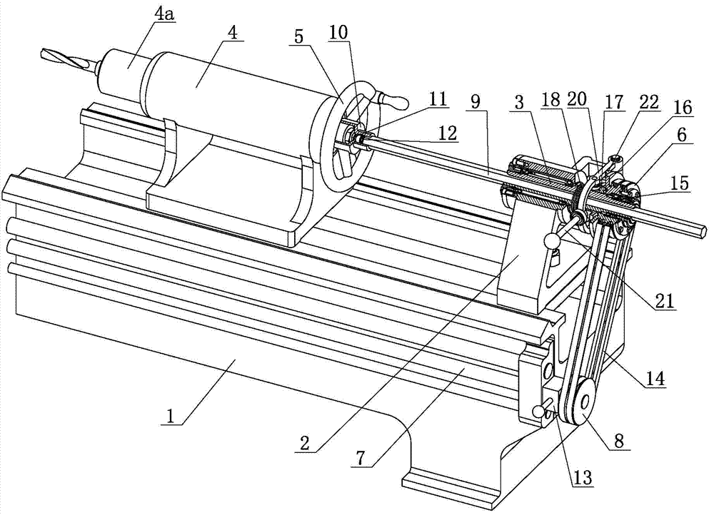
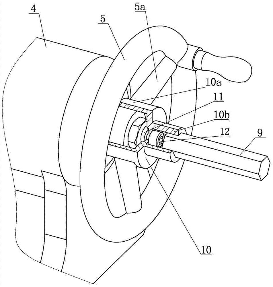
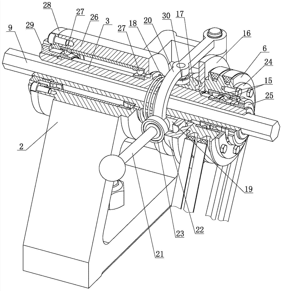
[0024] Such as figure 1 , figure 2 , image 3 , a kind of lathe tailstock power feeding device, is provided with power support 2 at the tail of lathe bed 1, is installed with drive shaft 3 on described power support, is provided with drive wheel 6 on the drive shaft, on lathe light bar The tail end of 7 is provided with the drive wheel 8 that rotates with feed rod, and described drive wheel drives described drive wheel to rotate; Described drive shaft is hollow shaft, passes through a can along drive shaft The shaft rod 9 that moves axially, the drive shaft drives the shaft rod to rotate, and the shaft rod drives the tailstock hand wheel 5 of the lathe at the front end to rotate and push the tailstock sleeve 4a to feed.
[0025] The tailstock 4 of the lathe is provided with a handwheel fork 10 for turning the handwheel of the tailstock; On the shaft of the tailstock handwheel, the front end of the handwheel fork is provided with a shifting head 10a which snaps into the spo...
Embodiment 2
[0034] Such as figure 1 , figure 2 , image 3 , Figure 4 , a lathe tailstock power feeding device with a chip breaking clutch, this embodiment adopts the lathe tailstock power feeding device described in Embodiment 1. A power support is arranged at the tail of the lathe bed, and a drive shaft is installed on the power support. The drive shaft drives the handwheel of the tailstock of the lathe to rotate, and a drive wheel is arranged on the drive shaft.
[0035]In this embodiment, a chip breaking clutch is provided on the drive shaft, the driving wheel is mounted on the driving shaft through a bearing 15, and the driving wheel is connected to the driving disc 16 of the chip breaking clutch; The driven disc and the drive shaft are axially slidably connected, and the connection method can adopt structures such as splines and flat keys. The driven disc 17 of the chip breaking clutch in this embodiment is connected with the drive shaft through splines. The driven disc of the ...
Embodiment 3
[0043] Such as Figure 5 , Figure 6 , Figure 7 , a power feeding device for a tailstock of a lathe with a stop mechanism. This embodiment adopts the power feeding device for a tailstock of a lathe with a chip breaking clutch described in Embodiment 2. A power support is provided at the tail of the lathe bed, and a drive shaft is installed on the power support, and the drive shaft drives the hand wheel of the tailstock of the lathe to rotate; a chip breaker clutch is provided on the drive shaft, and the breaker The chip clutch is provided with a driving plate, a driven plate and a clutch fork, and the clutch fork moves the driven plate of the chip breaking clutch to separate from the driving plate, and a fork handle is arranged on the clutch fork.
[0044] A pull rod 31 is arranged at the front end of the sleeve of the tailstock of the lathe, and a rotating rod 32 is arranged on the power support of the tailstock power feeding device of the lathe, and the rotation axis of t...
PUM
 Abstract
Description
Claims
Application Information
 - R&D
- Intellectual Property
- Life Sciences
- Materials
- Tech Scout
- Unparalleled Data Quality
- Higher Quality Content
- 60% Fewer Hallucinations
Browse by: Latest US Patents, China's latest patents, Technical Efficacy Thesaurus, Application Domain, Technology Topic, Popular Technical Reports.
© 2025 PatSnap. All rights reserved.Legal|Privacy policy|Modern Slavery Act Transparency Statement|Sitemap|About US| Contact US: help@patsnap.com


