Automatic drilling tool for welding yokes

A technology for drilling tooling and welding forks, which is applied in the directions of driving devices, boring/drilling, drilling/drilling equipment, etc. Hole efficiency and processing accuracy are improved, and the effect of automatic processing operation is realized

Inactive Publication Date: 2015-05-20
HEFEI WANXIANG QIANCHAO AUTO PARTS
12 Cites 7 Cited by

AI-Extracted Technical Summary

Problems solved by technology

[0002] In the field of auto parts processing, the welding fork of the brake needs to be drilled. The existing processing tooling canno...

Abstract

The invention relates to an automobile part machining device, in particular to an automatic drilling tool for welding yokes. The automatic drilling tool is arranged on an operation platform and comprises a workpiece clamping and rotating component and a drill bit fixing and pushing component, the workpiece clamping and rotating component comprises a coupling arranged on the operation platform and a driving motor connected with the coupling, and a group of workpiece clamping blocks are arranged at the end of a drive shaft chuck of the coupling; the drill bit fixing and pushing component comprises a guide rail, a slider sleeving the guide rail, a base arranged on the slider, a drill bit clamping block arranged on the upper portion of the base and a cylinder arranged on the operation platform and connected with the drill bit clamping block, and the drill bit clamping block clamps a drill bit to enable the axial extension line of the drill bit to pass through center points of the group of workpiece clamping blocks. By reasonable design of the structure of the workpiece clamping and rotating component and the drill bit fixing and pushing component, automatic machining operation of drilling of the welding yokes is realized, and drilling efficiency and machining precision are improved remarkably.

Application Domain

Work clamping meansFeeding apparatus +6

Technology Topic

Drive motorDrill bit +3

Image

  • Automatic drilling tool for welding yokes
  • Automatic drilling tool for welding yokes
  • Automatic drilling tool for welding yokes

Examples

  • Experimental program(1)

Example Embodiment

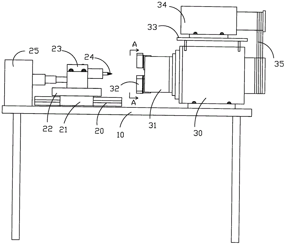
[0016] In order to further describe the present invention, the present invention will be further described in detail below with reference to the drawings and embodiments. Figure 1-3 A welding fork automatic drilling tool is shown, which is set on the operating table 10 and includes workpiece clamping and rotating parts and drill bit fixing and pushing parts, in which:
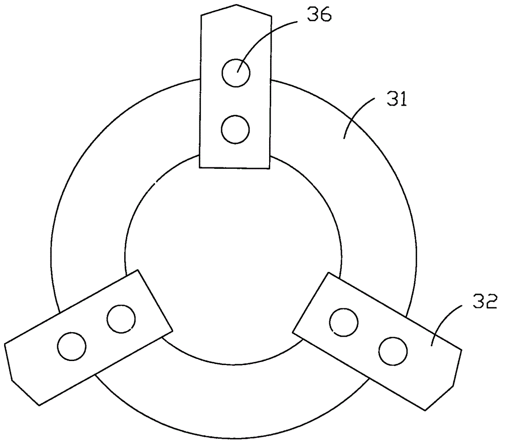
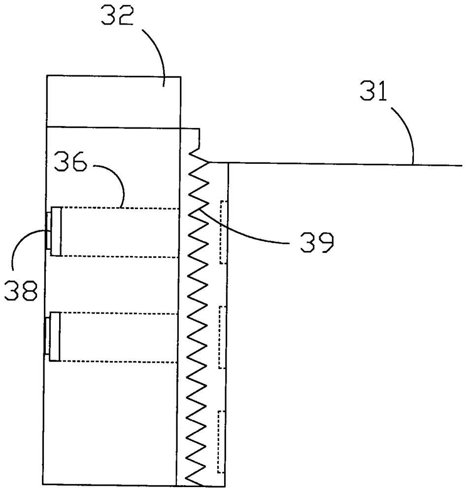
[0017] The workpiece clamping and rotating parts include a coupling 30 placed on the operating table 10, a drive motor 34 connected to the coupling 30 through a belt set 35 and placed on the upper part of the coupling 30, and a drive shaft of the coupling 30 A set of workpiece clamping blocks 32 is provided at the end of the chuck 31.
[0018] The drill bit fixing and advancing components include a guide rail 20 placed on the operating table 10, a slider 21 sleeved on the guide rail 20, a base 22 placed on the slider 21 and a drill holder placed on the upper part of the base 22 Block 23 and a cylinder 25 placed on the operating table 10 and connected to the drill bit clamping block 23. The drill bit clamping block 23 clamps the drill bit 24 so that the axial extension line of the drill bit 24 passes through the center point of a set of workpiece clamping blocks 32 .
[0019] The workpiece clamping block 32 and the end surface of the transmission shaft chuck 31 form a tooth-shaped matching relationship through a rack 39 to achieve a close or distance from the center point of the end surface of the transmission shaft chuck 31.
[0020] The workpiece clamping block 32 is provided with a bolt mounting hole 36, and the limiting bolt 38 passes through the bolt mounting hole 36 to fix the workpiece clamping block 32 and the drive shaft chuck 31.
[0021] The top of the coupling 30 is provided with a supporting plate 33, and the driving motor 34 is fixed on the supporting plate 33.
[0022] The above content is merely an example and description of the concept of the present invention. Those skilled in the art make various modifications or additions to the specific embodiments described or use similar methods to replace them, as long as they do not deviate from the concept of the invention. Or beyond the scope defined by the claims, all shall belong to the protection scope of the present invention.

PUM

no PUM

Description & Claims & Application Information

We can also present the details of the Description, Claims and Application information to help users get a comprehensive understanding of the technical details of the patent, such as background art, summary of invention, brief description of drawings, description of embodiments, and other original content. On the other hand, users can also determine the specific scope of protection of the technology through the list of claims; as well as understand the changes in the life cycle of the technology with the presentation of the patent timeline. Login to view more.
Why Eureka
Try Eureka