A new dc/ac arc welding device
A new type of arc welding technology, applied in arc welding equipment, welding equipment, manufacturing tools, etc., can solve the problems of increasing the difficulty of increasing the level of inverter control, increasing the current stress of power devices, reducing the overall reliability, etc. The effect of operability, improving commutation speed, and reducing control difficulty
- Summary
- Abstract
- Description
- Claims
- Application Information
AI Technical Summary
Problems solved by technology
Method used
Image
Examples
Embodiment 1
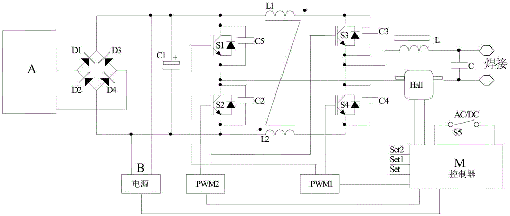
[0036] Embodiment 1, using the full-bridge inverter scheme:
[0037] Such as Figure 1a As shown, the low-voltage power supply A is isolated from the mains network;
[0038] The bridge rectifier circuit is composed of diodes D1, D2, D3, and D4, the output end is connected in parallel with a filter capacitor C1, and the input end is connected to the output end of the above-mentioned low-voltage power supply;
[0039] The bridge conversion circuit includes a full bridge circuit composed of switching elements S1, S2, S3, and S4, wherein the switching elements S1, S4 are arranged diagonally, the switching elements S2, S3 are arranged diagonally, and the switching element S1 is connected in parallel with a capacitor C5 The switching element S2 is connected in parallel with a capacitor C2, the switching element S3 is connected in parallel with a capacitor C3, the switching element S4 is connected in parallel with a capacitor C4, a coupling inductor L1 is connected in series between ...
Embodiment 2
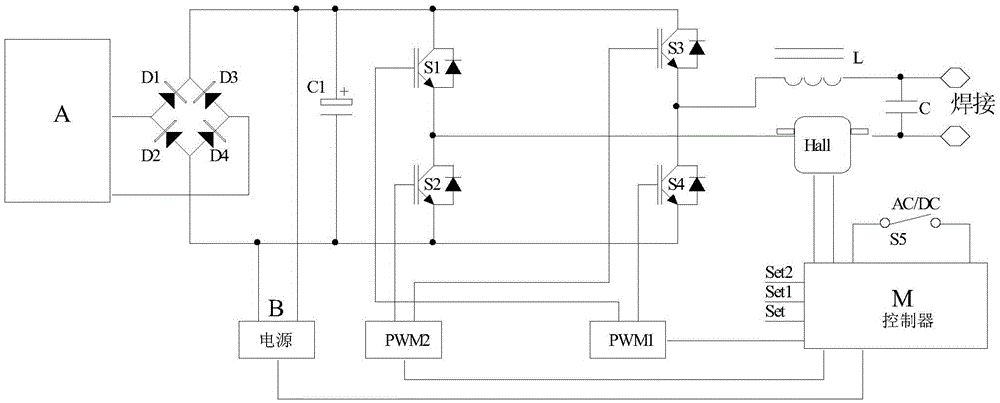
[0051] Embodiment 2 adopts the full-bridge inverter scheme;
[0052] Such as Figure 1b As shown, the circuit structure and working principle of Embodiment 2 are basically the same as Embodiment 1, the difference is that in the full bridge circuit of Embodiment 2, the inductors L1 and L2 are not coupled in series, and the switching elements S1, S2, S3, and S4 are not connected in parallel. Capacitors C2-C5; can realize the same function as embodiment 1.
Embodiment 3
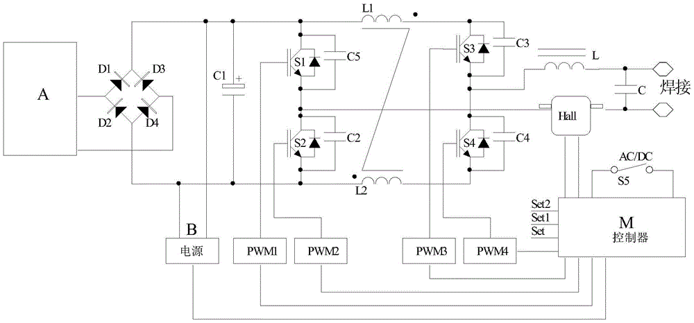
[0053] Embodiment 3, adopting the full-bridge inverter scheme;
[0054] Such as Figure 1c As shown, the structure and working principle of the main circuit of Embodiment 3 are basically the same as those of Embodiment 1, the difference is that the four switching elements in the full bridge circuit of Embodiment 3 use four PWM drivers for independent timing control.
[0055] In this system, when the AC / DC control switch S5 is set to DC output, such as Figure 2b As shown, the drivers PWM1 and PWM4 can be set separately to realize chopper constant current, while ensuring that the controllers PWM2 and PWM3 output 0 level. PWM1 and PWM4 can work in chopper mode at any fixed frequency above 2KHz at the same time, or only one of them can be used for chopping control, and the other can output high level, such as PWM1 for chopping and PWM4 for continuous output high level. At this time, the controller calculates the PWM1 duty ratio according to the set value Set and the sampling f...
PUM
 Abstract
Description
Claims
Application Information
 - R&D
- Intellectual Property
- Life Sciences
- Materials
- Tech Scout
- Unparalleled Data Quality
- Higher Quality Content
- 60% Fewer Hallucinations
Browse by: Latest US Patents, China's latest patents, Technical Efficacy Thesaurus, Application Domain, Technology Topic, Popular Technical Reports.
© 2025 PatSnap. All rights reserved.Legal|Privacy policy|Modern Slavery Act Transparency Statement|Sitemap|About US| Contact US: help@patsnap.com


