Novel DC/AC arc welding device

A new type of arc welding technology, applied in arc welding equipment, welding equipment, manufacturing tools, etc., can solve the problems of increasing the difficulty of one-stage inverter control, increasing the current stress of power devices, and reducing the overall reliability, so as to improve reliability Operability, increase the speed of reversing, and reduce the effect of control difficulty

Active Publication Date: 2015-05-20
HANGZHOU KAIERDA ELECTRIC WELDING MACHINE
View PDF5 Cites 2 Cited by
  • Summary
  • Abstract
  • Description
  • Claims
  • Application Information

AI Technical Summary

Problems solved by technology

The above-mentioned method of controlling the current, voltage and power by the primary inverter, and the current commutation control by the secondary inverter has the problem that it increases the difficulty of controlling the primary inverter, and it is easy to cause transformer magnetism when the current is rapidly transient. Saturation, causing the current stress of the power device to increase, reducing the overall reliability

Method used


Image

  • Novel DC/AC arc welding device
  • Novel DC/AC arc welding device
  • Novel DC/AC arc welding device

Examples


Embodiment 1

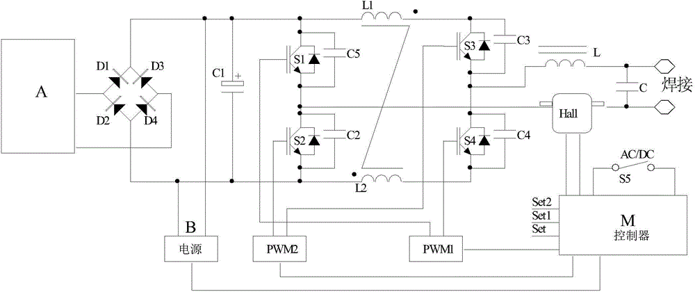
[0036] Embodiment 1, using the full-bridge inverter scheme:

[0037] Such as Figure 1a As shown, the low-voltage power supply A is isolated from the mains network;

[0038] The bridge rectifier circuit is composed of diodes D1, D2, D3, and D4, the output end is connected in parallel with a filter capacitor C1, and the input end is connected to the output end of the above-mentioned low-voltage power supply;

[0039] The bridge conversion circuit includes a full bridge circuit composed of switching elements S1, S2, S3, and S4, wherein the switching elements S1, S4 are arranged diagonally, the switching elements S2, S3 are arranged diagonally, and the switching element S1 is connected in parallel with a capacitor C5 The switching element S2 is connected in parallel with a capacitor C2, the switching element S3 is connected in parallel with a capacitor C3, the switching element S4 is connected in parallel with a capacitor C4, a coupling inductor L1 is connected in series between ...

Embodiment 2

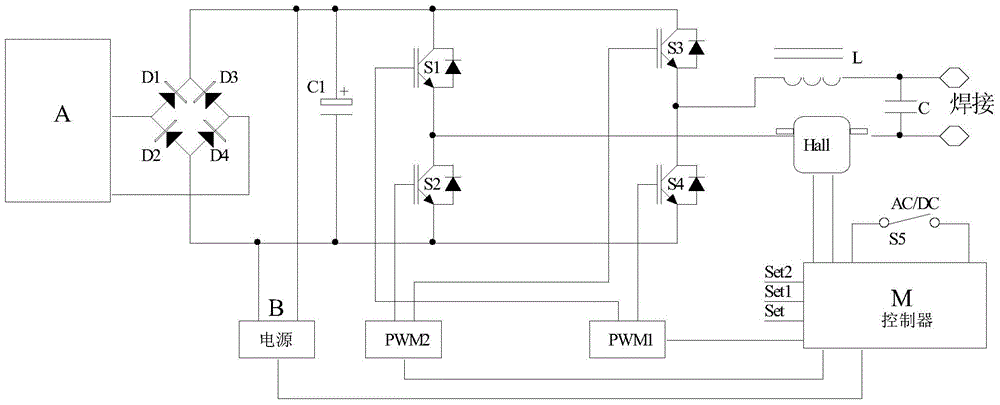
[0051] Embodiment 2 adopts the full-bridge inverter scheme;

[0052] Such as Figure 1b As shown, the circuit structure and working principle of Embodiment 2 are basically the same as Embodiment 1, the difference is that in the full bridge circuit of Embodiment 2, the inductors L1 and L2 are not coupled in series, and the switching elements S1, S2, S3, and S4 are not connected in parallel. Capacitors C2-C5; can realize the same function as embodiment 1.

Embodiment 3

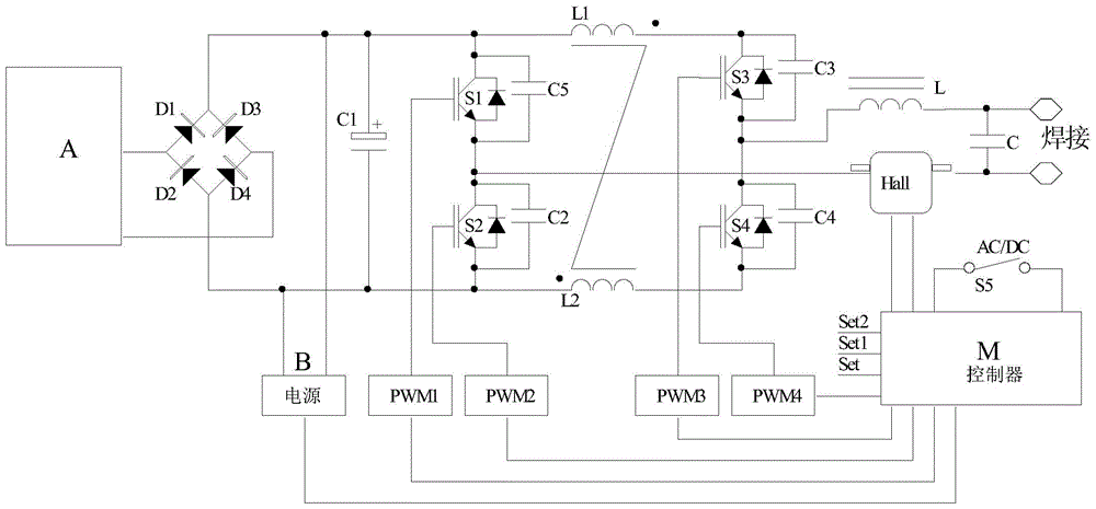
[0053] Embodiment 3, adopting the full-bridge inverter scheme;

[0054] Such as Figure 1c As shown, the structure and working principle of the main circuit of Embodiment 3 are basically the same as those of Embodiment 1, the difference is that the four switching elements in the full bridge circuit of Embodiment 3 use four PWM drivers for independent timing control.

[0055] In this system, when the AC / DC control switch S5 is set to DC output, such as Figure 2b As shown, the drivers PWM1 and PWM4 can be set separately to realize chopper constant current, while ensuring that the controllers PWM2 and PWM3 output 0 level. PWM1 and PWM4 can work in chopper mode at any fixed frequency above 2KHz at the same time, or only one of them can be used for chopping control, and the other can output high level, such as PWM1 for chopping and PWM4 for continuous output high level. At this time, the controller calculates the PWM1 duty ratio according to the set value Set and the sampling f...


PUM


Abstract

The invention relates to a novel DC/AC arc welding device. The DC/AC arc welding device can meet the welding technical requirements and is high in reliability and simple in structure. According to the technical scheme, the novel DC/AC arc welding device is characterized by comprising a low-voltage power supply, a bridge rectifier circuit, a bridge conversion circuit and a conversion control circuit, the output end of the low-voltage power supply is connected with the input end of the bridge rectifier circuit, the output end of the bridge rectifier circuit is connected with the input end of the bridge conversion circuit, the conversion control circuit is connected with the bridge conversion circuit and controls the bridge conversion circuit, and the output end of the conversion control circuit outputs welding current to the outside.

Description

technical field [0001] The invention relates to the technical field of inverter welding machines, in particular to a novel DC / AC arc welding device. Background technique [0002] Traditional inverter AC arc welding machines generally use two-level inverters. The main purpose of the first-level inverter is to control current, voltage and power, and at the same time have the functions of high-voltage isolation and voltage reduction. The main purpose of the second-level inverter is to change The direction of the current generates alternating current to meet the needs of the welding process. The above-mentioned method of controlling the current, voltage and power by the first-level inverter and the current commutation control by the second-level inverter has the problem that it increases the difficulty of controlling the first-level inverter, and it is easy to cause transformer magnetism when the current is rapidly transient. Saturation, causing the current stress of the power ...

Claims


Application Information

Patent Timeline
Patent Type & Authority Applications(China)
IPC IPC(8): B23K9/10
CPCB23K9/1043
Inventor 侯润石兰照丹王海辉王光辉贾想王青青吴勇健贾进涛
Owner HANGZHOU KAIERDA ELECTRIC WELDING MACHINE
Why Eureka
Try Eureka