Welding flux welding head

A technology of soldering and soldering head, applied in the field of soldering head, can solve the problems of waste of solder at the incision, high operation accuracy and high skill requirements of operators

Inactive Publication Date: 2015-05-20
SUZHOU AOPENG MACHINERY
View PDF4 Cites 0 Cited by
  • Summary
  • Abstract
  • Description
  • Claims
  • Application Information

AI Technical Summary

Problems solved by technology

[0003] In the prior art, in the electric welding operation process, the welding rod is cut or broken after one welding is completed. However, this method is easy to cause waste of solder at the cutting part; in addition, the traditional welding rod has high requirements for operation accuracy and operator skills in actual application. higher

Method used


Image

  • Welding flux welding head

Examples


Embodiment Construction

[0011] A detailed description will be given below of embodiments of the present invention. Although the present invention will be described and illustrated in conjunction with some specific embodiments, it should be noted that the present invention is not limited to these embodiments. On the contrary, any modification or equivalent replacement made to the present invention shall be included in the scope of the claims of the present invention.

[0012] In addition, in order to better illustrate the present invention, numerous specific details are given in the specific embodiments below. It will be understood by those skilled in the art that the present invention may be practiced without these specific details. In other instances, well-known components and structures are not described in detail so as to highlight the gist of the present invention.

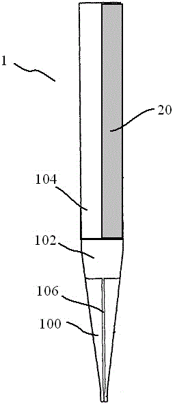
[0013] figure 1 Shown is a front view of a solder tip of one embodiment of the present invention. As shown in the figure, the s...


PUM


Abstract

The invention provides a welding flux welding head. The welding flux welding head is characterized in that the welding flux welding head at least comprises a welding head body which is used for welding a first workpiece to a to-be-welded part of a second workpiece and a welding flux body which is detachably arranged on the welding head body and used for providing welding flux when welding. Compared with the prior art, the welding flux welding head has the advantages of being convenient to operate, and capable of saving the welding flux.

Description

technical field [0001] The invention relates to the field of manufacturing, in particular to a solder welding head. Background technique [0002] In the field of processing, how to improve the efficiency and accuracy of batch processing has always been a hot technical issue in the industry. [0003] In the prior art, in the electric welding operation process, the welding rod is cut or broken after one welding is completed. However, this method is easy to cause waste of solder at the cutting part; in addition, the traditional welding rod has high requirements for operation accuracy and operator skills in actual application. higher. [0004] Therefore, it is imminent how to provide a welding head that is easy to operate and saves solder for small businesses or amateurs. Contents of the invention [0005] The purpose of the present invention is to provide a soldering tip, which is easy to operate and saves solder, and is especially suitable for small businesses or amateurs....

Claims


Application Information

Patent Timeline
Patent Type & Authority Applications(China)
IPC IPC(8): B23K35/02
CPCB23K35/0261
Inventor 詹自付
Owner SUZHOU AOPENG MACHINERY
Why Eureka
Try Eureka