Three-sided stable clamping mechanism

A clamping mechanism and stable technology, applied in the field of three-sided stable clamping mechanism, can solve problems such as clamping instability and achieve the effect of ensuring clamping stability

Inactive Publication Date: 2015-05-20
重庆迪科汽车科技集团有限公司
View PDF8 Cites 8 Cited by
  • Summary
  • Abstract
  • Description
  • Claims
  • Application Information

AI Technical Summary

Problems solved by technology

[0003] The existing simple and fast clamping fixtures mostly use two parallel jaws to clamp the workpiece.

Method used


Image

  • Three-sided stable clamping mechanism
  • Three-sided stable clamping mechanism

Examples


Embodiment Construction

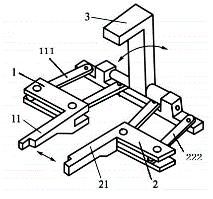
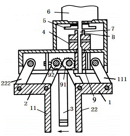
[0014] combined with figure 1 The shown three-sided stable clamping mechanism includes a frame on which an output shaft 7 driven by a motor 6 is arranged, and the rotating shaft is connected to a horizontal clutch 4 through a coupling 8, and the horizontal clutch 4 is connected to a screw rod 9, and the screw rod 9 is engaged with a Gear 91, gear 91 is meshed with No. 2 gear 92 of equal size, gear 91 is connected with horizontal first gripper 1 through the rotating shaft of gear 91, No. 2 gear 92 is connected with horizontal second gripper 2 through the rotating shaft of No. 2 gear 92 , the horizontal first jaw 1 is hinged to the frame through the first parallelogram 111, the horizontal second jaw 2 is hinged to the frame through the second parallelogram 222, the first horizontal jaw 1 The clamping rod 11 is parallel to the second clamping rod 22 between the horizontal second clamping jaws 2 , and the working surfaces of the first clamping rod 11 and the second clamping rod 22...


PUM


Abstract

The invention relates to mechanical clamping mechanisms, in particular to a three-sided stable clamping mechanism. The three-sided stable clamping mechanism comprises a rack, an output shaft driven by a motor is arranged on the rack, the output shaft is connected with a horizontal clutch, the horizontal clutch is connected with a screw, the screw is meshed with a gear, the gear is meshed with an equal-sized second gear, the gear is connected with a horizontal first clamping jaw through a rotating shaft, and the second gear is connected with a horizontal second clamping jaw through another rotating shaft, wherein the output shaft is fixedly sleeved with a vertical gear, the vertical gear is connected with a vertical clutch, and the vertical clutch is connected with a vertical clamping jaw. The invention aims at providing the clamping mechanism which is fast to clamp and more stable.

Description

technical field [0001] The invention relates to a mechanical clamping mechanism, in particular to a three-sided stable clamping mechanism. Background technique [0002] The device used to fix the processing object in the process of mechanical manufacturing so that it occupies the correct position to accept construction or inspection, also known as fixture. In a broad sense, any process in the process, the device used to install the workpiece quickly, conveniently and safely, can be called a fixture. Such as welding fixtures, inspection fixtures, assembly fixtures, machine tool fixtures, etc. Among them, machine tool fixtures are the most common, often referred to as fixtures. When processing a workpiece on a machine tool, in order to make the surface of the workpiece meet the technical requirements such as the size, geometric shape, and position accuracy with other surfaces specified in the drawing, the workpiece must be installed (positioned) and clamped (clamped) before ...

Claims


Application Information

Patent Timeline
IPC IPC(8): B23Q3/06
CPCB23Q3/06
Inventor 曹建国
Owner 重庆迪科汽车科技集团有限公司
Why Eureka
Try Eureka