Injection mould of automatically cutting side gate in mould

A technology of automatic cutting and injection moulding, which is applied in the field of injection moulds and injection moulds with automatic cutting of side gates in the mould. good stability

Inactive Publication Date: 2015-05-20
HENAN POLYTECHNIC INST
View PDF5 Cites 5 Cited by
  • Summary
  • Abstract
  • Description
  • Claims
  • Application Information

AI Technical Summary

Problems solved by technology

[0007] Due to the adoption of a two-stage push-out mechanism, the cost of the mold increases
In addition, the automatic cut-off gate structure has high requirements

Method used


Image

  • Injection mould of automatically cutting side gate in mould
  • Injection mould of automatically cutting side gate in mould
  • Injection mould of automatically cutting side gate in mould

Examples


Embodiment Construction

[0033] The present invention will be specifically introduced below in conjunction with the accompanying drawings and specific embodiments.

[0034] The injection mold for automatically cutting off the side gate in the mold of the present invention includes two parts, a fixed mold and a movable mold, which will be described separately below.

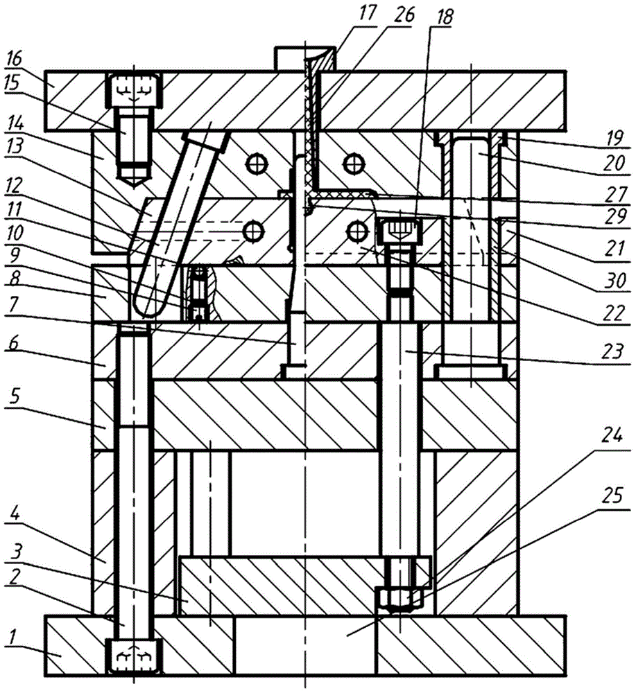
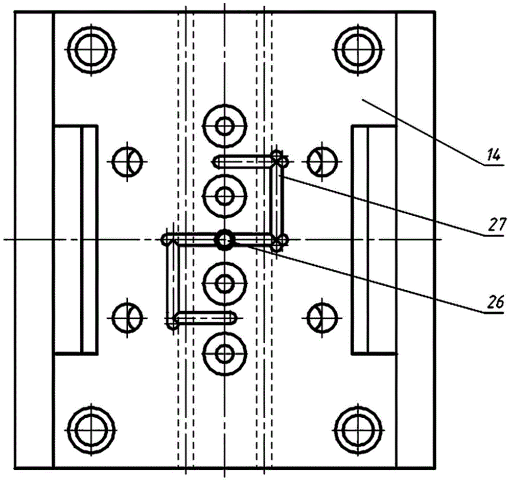
[0035] refer to figure 1 and figure 2 , fixed mold comprises: fixed mold base plate 16, fixed template 14 and fixed mold guide sleeve 19. The fixed template 14 is fixed on the bottom surface of the fixed mold seat plate 16 by screws 15, and the fixed template 14 is used to form the top of the product mold cavity. The fixed die guide sleeve 19 is also fixed on the bottom surface of the fixed die seat plate 16, and the fixed die guide sleeve 19 is vertically arranged. A sprue sleeve 17 is arranged on the fixed template 14 .

[0036] refer to figure 1 and figure 2 , The movable mold includes: a movable mold seat plate 1, a spacer 4, ...


PUM


Abstract

The invention discloses an injection mould of automatically cutting a side gate in the mould. The injection mould comprises a fixed mould and a moving mould, and is characterized in that a gating system is arranged on the fixed mould, a stripper plate ejecting mechanism is arranged on the moving mould, a side core-pulling mechanism is arranged between the fixed mould and the moving mould; when the mould is closed, a product mould cavity is communicated with the gating system, when the mould is opened, the side core-pulling mechanism completes product core pulling, and the stripper plate ejecting mechanism is used for automatically cutting a solidified material formed in the side gate in the mould and then delaying the ejection of a product on a core. The injection mould has the beneficial effects of being simple in structure, convenient to make and excellent use stability; by only requiring one-stage ejecting mechanism, because a delay distance is formed between the stripper plate and the bottom of the product and the maximum opening distance of a sliding block is less than the size of a runner in an opening direction of the sliding block, the stripper plate ejecting mechanism can be used for ejecting the solidified material formed in the gating system and snapping the solidified material formed in the side gate, and then ejecting the product, so that the automatic cutting of the side gate in the mould is realized.

Description

technical field [0001] The invention relates to an injection mold, in particular to an injection mold for automatically cutting off a side gate in a mold, and belongs to the technical field of molds. Background technique [0002] In the ordinary runner gating system, the point gate is easy to realize automatic cutting when the mold is opened, and the remaining traces of the gate on the part are small, so it is widely used. But the point gate must use double parting surface injection mold, the mold structure is complicated and the cost is high. The latent gate, also known as the shear gate, is a variation of the point gate. The runner of the latent gate is located on the parting surface of the mold, and the gate sneaks into one side of the parting surface and enters the cavity along an oblique direction. , so that not only the gate can be automatically cut off when the mold is opened, but also the position is concealed, so that there is no trace of the gate on the outer surf...

Claims


Application Information

Patent Timeline
IPC IPC(8): B29C45/33B29C45/38
CPCB29C45/33B29C45/38
Inventor 熊毅赵岩郭威邓晓张成光张玉华崔庚彦郑晓东李延军
Owner HENAN POLYTECHNIC INST
Why Eureka
Try Eureka