

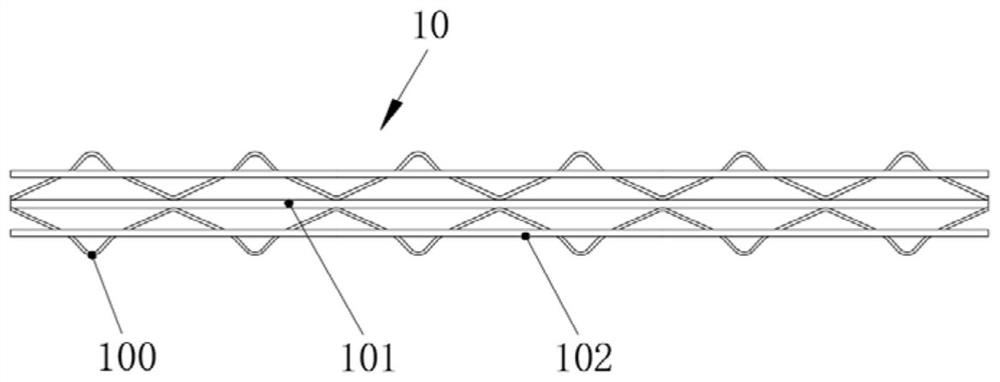
Truss footing cutting device
A cutting device and truss technology, applied in the field of truss processing, can solve the problems of high labor intensity and low production efficiency, and achieve the effects of high automation, improving production efficiency, reducing labor intensity and potential safety hazards
- Summary
- Abstract
- Description
- Claims
- Application Information
AI Technical Summary
Problems solved by technology
Method used
Image

Examples
Embodiment 2
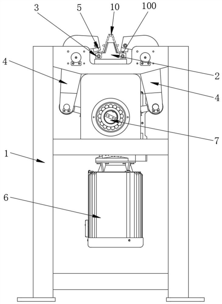
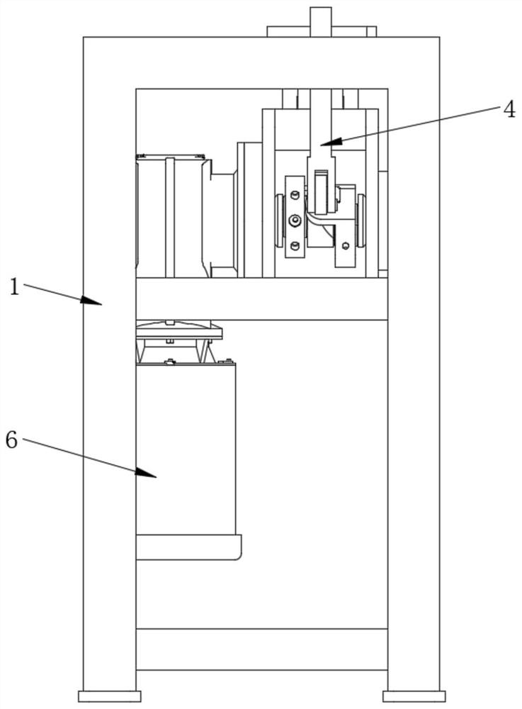
[0044] This embodiment provides a truss foot cutting device, which differs from Embodiment 1 in that the cutting arm of this embodiment is not rotatably disposed on the frame, but is slidably disposed on the frame, and the driving member is used to drive The cutting arm slides, and in this embodiment, no transmission assembly is provided.
[0045] Specifically, a slide rail may be provided on the frame, and a slide block is correspondingly provided on the cutting arm, and the driver drives the cutting arm to slide vertically, and the slide block and the slide rail can serve the purpose of guiding and stabilizing support.
[0046] At the same time, the driving member in this embodiment can be an air cylinder or an oil cylinder, and the output end of the air cylinder or oil cylinder is connected to the cutting arm. The driving part can be set in two, and each driving part is drivingly connected to a cutting arm respectively, and the two driving parts preferably run synchronously...
PUM
 Abstract
Description
Claims
Application Information