An Injection Mold with Automatic Cut-off Side Gate in Mold

An automatic cut-off and injection mold technology, applied in the field of molds, can solve the problems of automatic gate cut-off, mold cost increase, etc., and achieve the effect of simple structure, easy assembly, and good use stability

Inactive Publication Date: 2016-09-07
HENAN POLYTECHNIC INST
View PDF5 Cites 0 Cited by
  • Summary
  • Abstract
  • Description
  • Claims
  • Application Information

AI Technical Summary

Problems solved by technology

[0007] Due to the adoption of a two-stage push-out mechanism, the cost of the mold increases
In addition, the automatic cut-off gate structure has high requirements on the position of the gate. When the joint between the product and the gate is not suitable for setting a push rod, the automatic gate cut-off cannot be realized.

Method used


Image

  • An Injection Mold with Automatic Cut-off Side Gate in Mold
  • An Injection Mold with Automatic Cut-off Side Gate in Mold
  • An Injection Mold with Automatic Cut-off Side Gate in Mold

Examples


Embodiment Construction

[0033] The following describes the present invention in detail with reference to the drawings and specific embodiments.

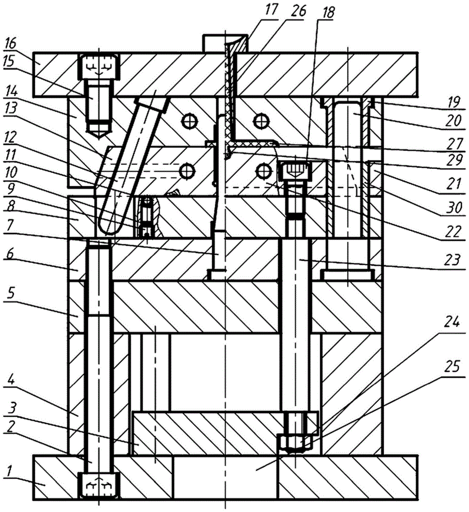
[0034] The injection mold for automatically cutting the side gate in the mold of the present invention includes two parts, a fixed mold and a movable mold, which will be described separately below.

[0035] Reference figure 1 with figure 2 , The fixed mold includes: a fixed mold base plate 16, a fixed mold plate 14 and a fixed mold guide sleeve 19. The fixed mold plate 14 is fixed on the bottom surface of the fixed mold seat plate 16 by screws 15. The fixed mold plate 14 is used to form the upper part of the product mold cavity. The fixed mold guide sleeve 19 is also fixed on the bottom surface of the fixed mold seat plate 16, and the fixed mold guide sleeve 19 is vertically arranged. A sprue sleeve 17 is provided on the fixed template 14.

[0036] Reference figure 1 with figure 2 The movable mold includes: a movable mold seat plate 1, a cushion block 4, a sup...


PUM


Abstract

The invention discloses an injection mold for automatically cutting off the side gate in the mold, which includes two parts: a fixed mold and a movable mold. There is a lateral core-pulling mechanism between the mold and the movable mold; when the mold is closed, the cavity of the product is connected to the gating system; The formed condensate is automatically cut off in the mold and then the product on the core is delayed to be pushed out. The advantages of the present invention are: simple structure, convenient manufacture, and good stability in use; only one stage of push-out mechanism is required, since there is a delay distance between the push piece plate and the bottom of the product and the maximum opening distance of the slider is less than that of the shunt channel. The size of the opening direction of the slider, so the ejector plate push-out mechanism can first push out the aggregate formed in the gating system and break the aggregate formed in the side gate, and then push out the product, realizing the automatic cutting of the side pouring in the mold mouth.

Description

Technical field [0001] The invention relates to an injection mold, in particular to an injection mold with a side gate automatically cut off in the mold, and belongs to the technical field of molds. Background technique [0002] In the ordinary runner gating system, the point gate is easy to be automatically cut when the mold is opened, and the residual gate marks on the part are small, and it is widely used. However, the point gate must use a double parting surface injection mold, which has a complex structure and high cost. Latent gate is also called shear gate. It is a variation of point gate. The runner of the latent gate is located on the parting surface of the mold. The gate sneaks into one side of the parting surface and enters the cavity in an oblique direction. , In this way, the gate can be automatically cut when the mold is opened, and the position is hidden, so that the outer surface of the product has no gate marks. But the latent gate is difficult to process, and ...

Claims


Application Information

Patent Timeline
Patent Type & Authority Patents(China)
IPC IPC(8): B29C45/33B29C45/38
CPCB29C45/33B29C45/38
Inventor 熊毅赵岩郭威邓晓张成光张玉华崔庚彦郑晓东李延军
Owner HENAN POLYTECHNIC INST
Why Eureka
Try Eureka