Laser marking equipment

A laser marking and equipment technology, applied in the field of workpiece clamping, can solve the problems of high labor intensity and low work efficiency of workers, and achieve the effect of overcoming high labor intensity, simple structure and reasonable disassembly.

Inactive Publication Date: 2015-05-20
封新娥
View PDF0 Cites 0 Cited by
  • Summary
  • Abstract
  • Description
  • Claims
  • Application Information

AI Technical Summary

Problems solved by technology

[0003] The object of the present invention is to overcome the deficiencies in the prior art, and provide a laser marking equipment with a simple, ingenious and reasonable structure, which can be easily disassembled. The problem of inefficiency
[0005] Compared with the prior art, the present invention has the advantages of providing a simple, ingenious and reasonable laser marking equipment that is easy to disassemble. low problem

Method used


Image

  • Laser marking equipment
  • Laser marking equipment
  • Laser marking equipment

Examples


Embodiment Construction

[0012] The present invention will be further described below with reference to the specific drawings and embodiments.

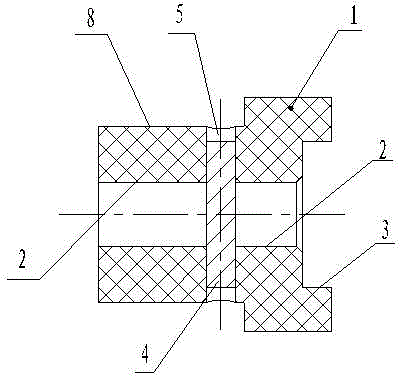
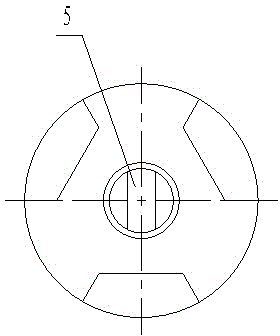
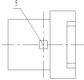
[0013] like Figure 1-4 As shown, a laser marking equipment of the present invention is characterized in that it includes a positioning member 1 and a magnetic steel 4. The positioning member 1 is provided with a through hole 2, and one end of the positioning member 1 is provided with a stepped hole 3. The through The hole 2 and the step hole 3 are on the same axis, and the other end of the positioning member 1 is provided with a clamping circle 8, and the positioning member 1 is provided with a square hole 5 passing through the axial direction of the positioning member 1. The axis of the hole 5 is perpendicular to the axis of the through hole 2 and intersects. The magnetic steel 4 with an interference fit with the square hole 5 is arranged in the square hole 5. The magnetic steel 4 is square. The clamping circle 8 on the piece 1 is placed on the three-jaw c...


PUM


Abstract

The invention relates to the field of workpiece clamping, in particular to laser marking equipment comprising a positioning member and a magnetic steel. The positioning member is provided with a through hole; one end of the positioning member is provided with a stepped hole, the through hole and the stepped hole are coaxial, the other end of the positioning member is provided with a clamping ring, the positioning member is provided with a squared hole penetrating the positioning member axially, and the axis of the squared hole is perpendicular to that of the through hole in a crossed manner; the squared hole is provided with the magnetic steel, inside, which is in clearance fit with the squared hole, and the magnetic steel is in a cube shape. The laser marking equipment is simple in structure, ingenious and reasonable, and the problems that in the prior art, the work intensity of workers is high and working efficiency is low are overcome effectively.

Description

technical field [0001] The invention relates to the technical field of workpiece clamping, in particular to laser marking equipment. Background technique [0002] Laser marking technology has been used in all walks of life. With the continuous spread of laser marking application fields, the requirements for laser marking efficiency are getting higher and higher. Currently, laser marking of cylindrical sensor parts with hexagonal surfaces uses The equipment is to put the workpiece into the three-jaw chuck, tighten the three-jaw chuck to clamp the workpiece, and then control the three-jaw chuck to rotate through the motor to mark the designated surface of the hexagonal surface of the sensor. After the marking is completed, loosen Open the three-jaw chuck to take out the workpiece, and then mark the next workpiece, the labor intensity of the workers is high, and the work efficiency is low. Contents of the invention [0003] The object of the present invention is to overcome ...

Claims


Application Information

Patent Timeline
Patent Type & Authority Applications(China)
IPC IPC(8): B41J3/407B41J2/435
Inventor 封新娥
Owner 封新娥
Why Eureka
Try Eureka