Zipper shearing equipment

A zipper cutting equipment and thread connection technology are applied in the cutting of textile materials, textiles and papermaking, etc., which can solve the problems of low efficiency of semi-automatic processing and achieve the effect of improving production efficiency.

Inactive Publication Date: 2015-05-20
安徽凯恩特科技有限公司
View PDF0 Cites 1 Cited by
  • Summary
  • Abstract
  • Description
  • Claims
  • Application Information

AI Technical Summary

Problems solved by technology

[0003] The technical problem to be solved by the present invention is to provide a zipper cutting device to solve the problem of low efficiency of manual processing or semi-automatic processing

Method used


Image

  • Zipper shearing equipment

Examples


Embodiment Construction

[0024] In the following, numerous specific details are set forth in order to provide a thorough understanding of the concepts underlying the described embodiments. It will be apparent, however, to one skilled in the art that the described embodiments may be practiced without some or all of these specific details. In other instances, well known processing steps have not been described in detail.

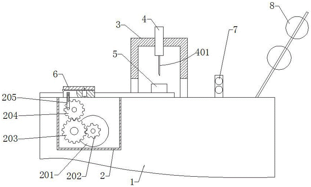
[0025] like figure 1 As shown, it includes the frame 1, the driver 2, the support seat 3, the punch 4, the spacer 5, the movable clamp 6, the material guide wheel 7, and the material preparation wheel 8. The driver 2 is located on the left side of the frame 1. The two are connected by threads, the support seat 3 is located at the center of the top of the frame 1, the two are connected by threads, the punch 4 is located at the inner center of the support seat 3, and the two are movably connected, and the pad 5 is located at the center of the lower end of the punch 4, which is connecte...


PUM


Abstract

The invention discloses zipper shearing equipment. The zipper shearing equipment comprises a rack, a driver, a supporting base, a puncher pin, a cushion block, a movable material clamping device, material guiding wheels and material preparing wheels. The driver is located on the left side in the rack and in threaded connection with the rack, the supporting base is located in the center of the top of the rack and in threaded connection with the rack, the puncher pin is located in the center in the supporting base and movably connected with the supporting base, the cushion block is located in the center of the lower end of the puncher pin and in threaded connection with the rack, the movable material clamping device is located in the center of the left side of the top of the rack and movably connected with the rack, the material guiding wheels are located in the center of the right side of the top of the rack and in threaded connection with the rack, and the material preparing wheels are located in the center of the right end of the top of the rack and in threaded connection with the rack. Compared with the prior art, it is only required to install a zipper cotton tape into a feeding wheel, the cotton tape is conveyed to the lower end of the puncher pin through the material guiding wheels, the movable material clamping device pulls the cotton tape to a certain length, and the puncher pin cuts off the cotton tape, so that full automatic shearing is achieved, and the production efficiency is improved.

Description

technical field [0001] The invention relates to a cutting device, in particular to a zipper cutting device. Background technique [0002] Zipper is an indispensable item in life, and it is also used on a large scale. However, at present, the cutting of the cloth tape of the zipper still needs to be cut manually with scissors and manually operated by semi-automatic equipment, so that the production requires a lot of labor and material resources to complete. , and the processing efficiency is extremely low and cannot meet the production requirements. In view of the above defects, it is necessary to design a zipper cutting device. Contents of the invention [0003] The technical problem to be solved by the present invention is to provide a zipper cutting device to solve the problem of low efficiency of manual processing or semi-automatic processing. [0004] In order to solve the above-mentioned technical problems, the technical solution of the present invention is: a zipper...

Claims


Application Information

Patent Timeline
Patent Type & Authority Applications(China)
IPC IPC(8): D06H7/00
CPCD06H7/00
Inventor 张丕波何延强张红杰
Owner 安徽凯恩特科技有限公司
Why Eureka
Try Eureka