Axial turbine

An axial-flow turbine and turbine technology, which is applied to gas turbine devices, mechanical equipment, engine components, etc., can solve problems such as promoting mixing loss, undisclosed relationship between turbine operating states, and inability to give full play to the steering effect of guide plates, etc. The effect of mixing loss

Inactive Publication Date: 2015-05-20
MITSUBISHI HITACHIPOWER SYST LTD
View PDF4 Cites 7 Cited by
  • Summary
  • Abstract
  • Description
  • Claims
  • Application Information

AI Technical Summary

Problems solved by technology

[0007] However, Patent Document 1 does not disclose the relationship between the operating state of the turbine and the guide plate, and there is a possibility that the effect of the guide plate on diverting the leakage flow cannot be sufficiently exhibited depending on the operating state of the turbine.
In particular, when the operating state of the turbine changes and the direction of the main flow changes, the optimal direction for installing the guide plate changes, so that due to the installation of the guide plate, there will be a mismatch between the direction of the leakage flow and the direction of the main flow, and it is considered that has the potential to conversely contribute to mixed losses

Method used


Image

  • Axial turbine
  • Axial turbine
  • Axial turbine

Examples


Embodiment 1

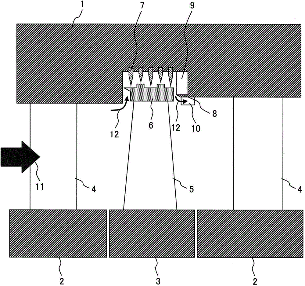
[0030] figure 1 as well as figure 2 The stage structure of the steam turbine according to Embodiment 1 of the present invention is shown. The turbine stage of the steam turbine of the present embodiment includes: a turbine rotor 3 rotatably supported; a turbine rotor blade 5 fixed to the turbine rotor 3; a shroud 6 provided at the front end of the turbine rotor blade 5; Diaphragm outer ring 1 opposite with a gap; radial sealing tab 7 , which is in the gap between shroud 6 and diaphragm outer ring 1 so as to protrude from diaphragm outer ring 1 in the radial direction of turbine rotor 3 The axial sealing fin 8 is set in the gap between the shroud 6 and the outer ring 1 of the diaphragm in a manner protruding from the outer ring 1 of the diaphragm along the rotational axis of the turbine rotor 3; a plurality of ribs 9, It is arranged in the gap between the shroud 6 and the diaphragm outer ring 1 in such a way that it is clamped by the diaphragm outer ring 1 and the axial seal...

Embodiment 2

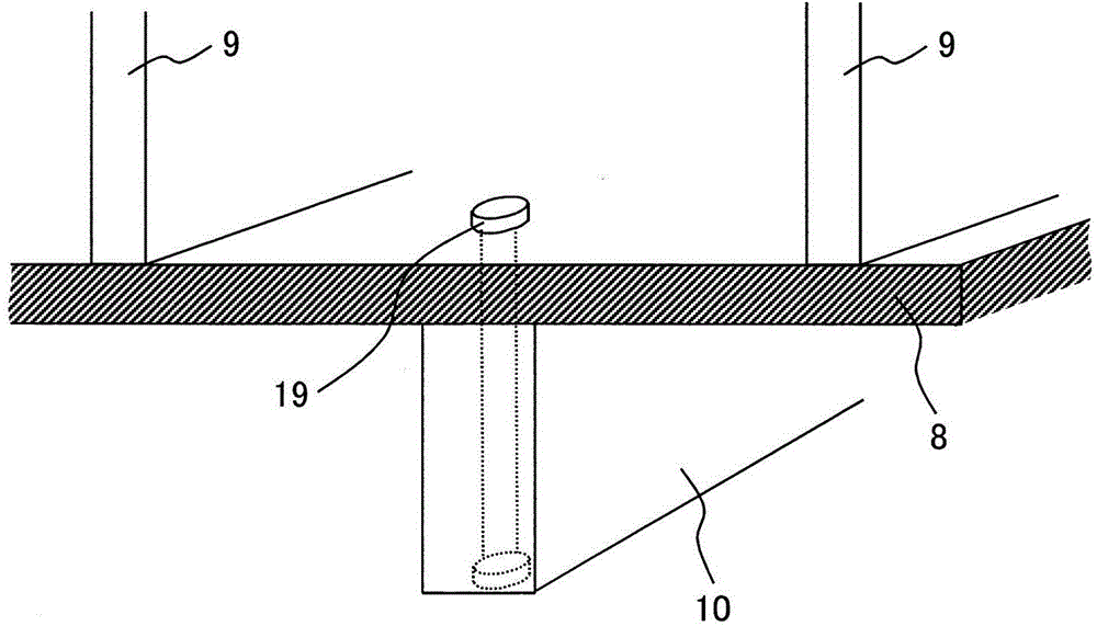
[0049] Figure 10 as well as Figure 11 The stage structure of the steam turbine according to Example 2 of the present invention is shown. in addition, Figure 12 express Figure 11 The top view of the guide plate 10. The turbine stage of the steam turbine of the present embodiment has: a turbine rotor 3 rotatably supported; a turbine rotor blade 5 fixed to the turbine rotor 3; a shroud 6 provided at the front end of the turbine rotor blade 5; Diaphragm outer ring 1 opposite with a gap; radial sealing tab 7 , which is in the gap between shroud 6 and diaphragm outer ring 1 so as to protrude from diaphragm outer ring 1 in the radial direction of turbine rotor 3 The axial sealing fin 8 is set in the gap between the shroud 6 and the outer ring 1 of the diaphragm in a manner protruding from the outer ring 1 of the diaphragm along the rotational axis of the turbine rotor 3; a plurality of ribs 9, It is set in the gap between the shroud 6 and the outer ring of the diaphragm 1 in...


PUM


Abstract

An axial turbine includes a plurality of ribs 9 provided in such a way as to be sandwiched between the diaphragm outer ring 1 and the axial seal fin 7 in the gap between the shroud 6 and the diaphragm outer ring 1, the ribs 9 being extended from the diaphragm outer ring 1 toward the shroud 6 in the radial direction of the rotor 3 and in the direction of the rotation axis thereof, and a guide plate 10 provided in such a way as to be present along the axial seal fin 7 and a face of the diaphragm outer ring 1, opposed to the rotor 3, so as to be extended in the rotation radial direction of the rotor 3.

Description

technical field [0001] The present invention relates to axial turbines such as gas turbines and steam turbines used in power generation facilities and the like. Background technique [0002] Gas turbines and steam turbines used in power generation equipment, etc. are roughly classified into the following three types according to the flow direction of their working fluid: axial flow turbines, in which the fluid flows along the rotational axis of the turbine; and axial flow turbines, in which the fluid diffuses obliquely from the rotational axis A diagonal flow turbine in which the fluid flows in a radial direction; a radial flow turbine in which the fluid flows radially along the rotation. Among them, axial flow turbines are particularly suitable for medium-to-large-capacity power generation equipment, and are generally widely used in steam turbines and the like in large-scale thermal power plants. [0003] However, in recent years, further improvement in power generation ef...

Claims


Application Information

Patent Timeline
Patent Type & Authority Applications(China)
IPC IPC(8): F01D11/02F02C7/28
CPCF01D5/145F01D5/225F01D11/08F01D17/162F05D2220/31F05D2250/411F01D17/08F01D17/12F02C7/28F02C9/16
Inventor 福岛久刚柴田贵范濑川清李宏元
Owner MITSUBISHI HITACHIPOWER SYST LTD
Why Eureka
Try Eureka