
Portable power pack, fuel/air supply for the portable power pack, uniflow scavenging micro-engine for the portable power pack and operation method thereof

a portable power pack and micro-engine technology, applied in the field of portable power packs, can solve the problems of insufficient capacity of the power pack to block multiple use, complicated power pack existing, etc., and achieve the effect of convenient carrying and us

Inactive Publication Date: 2010-03-02
KOREA INST OF ENERGY RES
View PDF22 Cites 1 Cited by
  • Summary
  • Abstract
  • Description
  • Claims
  • Application Information

AI Technical Summary

Benefits of technology

The solution provides a compact, efficient power pack with increased energy density, reduced manufacturing costs, and improved heat efficiency, enabling longer operation times for portable devices and autonomous robots without the need for frequent recharging.

Problems solved by technology

However, the existing power pack is too complicated to reduce its size.
Even if the power pack is miniaturized, the capacity thereof is insufficient to block the multiple use.

Method used


Image

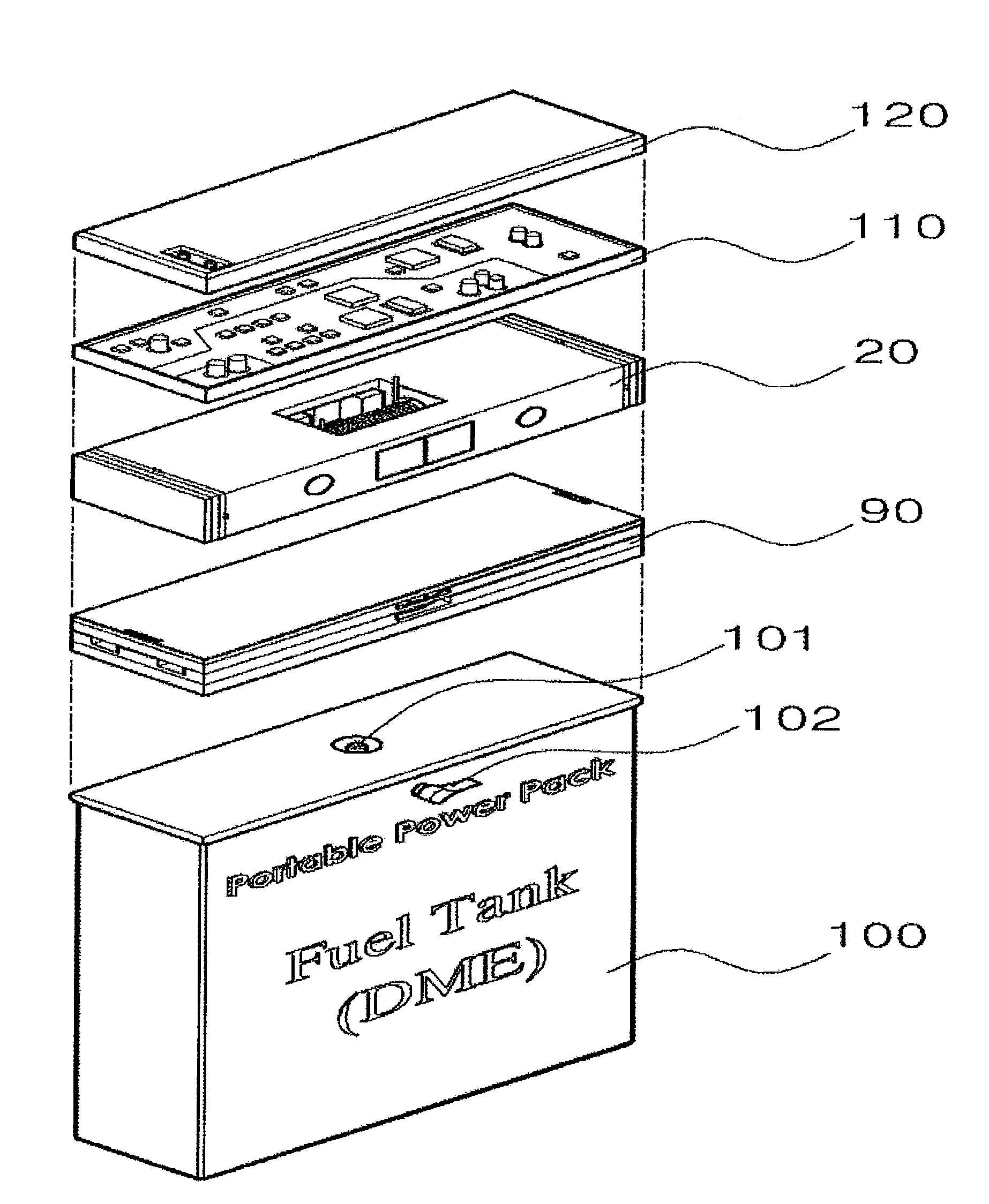
  • Portable power pack, fuel/air supply for the portable power pack, uniflow scavenging micro-engine for the portable power pack and operation method thereof
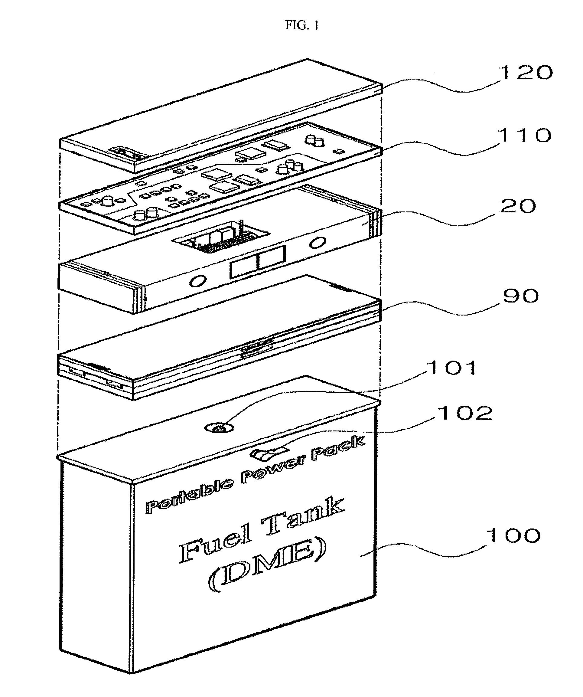
  • Portable power pack, fuel/air supply for the portable power pack, uniflow scavenging micro-engine for the portable power pack and operation method thereof
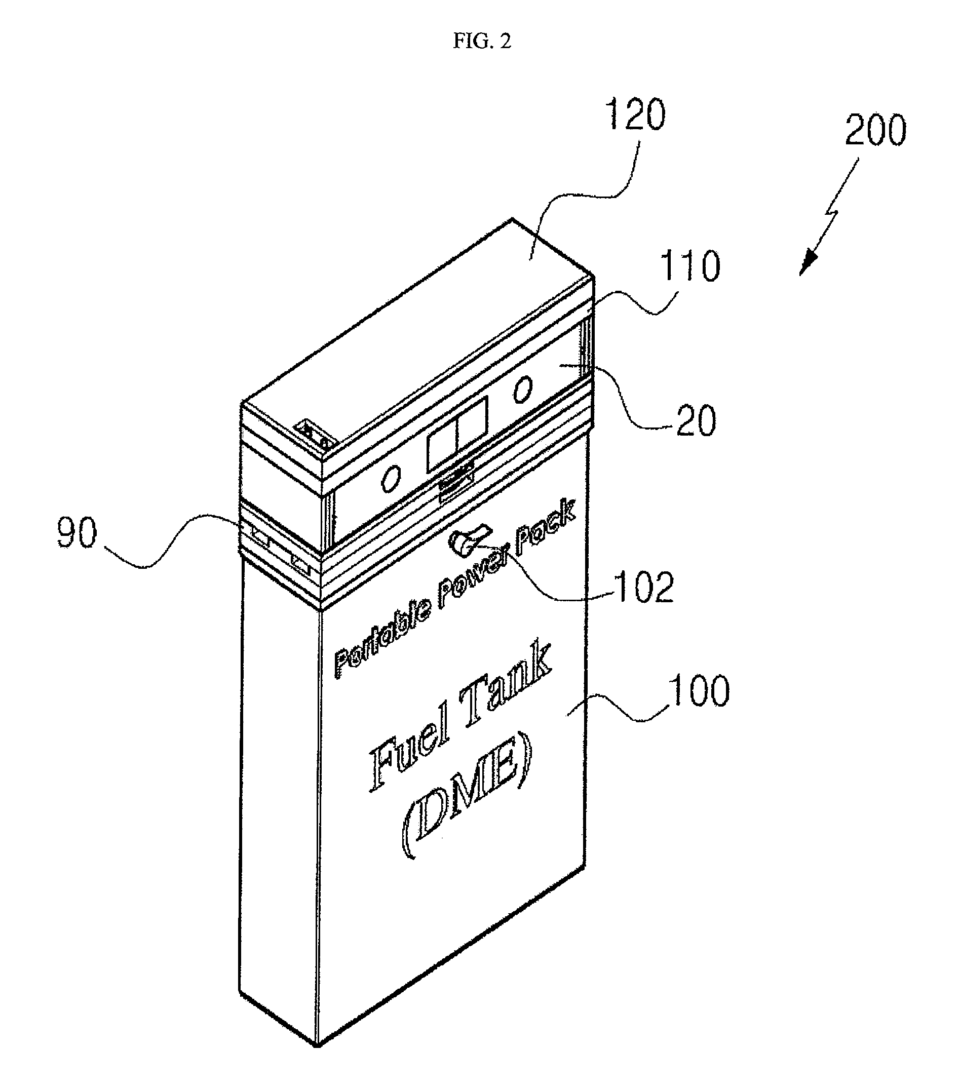
  • Portable power pack, fuel/air supply for the portable power pack, uniflow scavenging micro-engine for the portable power pack and operation method thereof

Examples


second embodiment

[0089]FIG. 19 is a flowchart illustrating a method of operating the uniflow scavenging micro-engine.

[0090]As shown in FIG. 19, according to the method of operating the uniflow scavenging micro-engine 20 of the invention, mixed gas including fuel and air is fed to the inlet units 1 and 8 by compression in S100.

[0091]In S200, as mixed gas is fed to the inlet units 1 and 8, the valves 2 and 7 are opened and mixed gas is introduced into the combustion chamber. In S300, mixed gas introduced through the inlet unit 1 explodes, ignited by the igniter 14 of the glow plug 3.

[0092]The exploded region inside the combustion chamber 4 expands due to the explosion, thereby sliding the piston 5 in one direction, and the pressure of the exploded region rises, thereby closing the valve 2 due to pressure difference in S400.

[0093]In S500, the inside region of the combustion chamber 4, to which the piston 4 is slid, is compressed to close the valve 7 due to the rise of pressure, thereby stopping mixed g...

third embodiment

[0118]Hereinafter a method of operating the uniflow scavenging micro-engine will be described more fully with reference to the accompanying drawing.

[0119]FIG. 27 is a flowchart illustrating a method of operating the third embodiment of the uniflow scavenging micro-engine.

[0120]Referring to FIG. 27, according to the method of operating the uniflow scavenging micro-engine 20 of the invention, mixed air including fuel and air is delivered from outside through the inlet holes 211 of the cylinder block heads 210 and is introduced into the cylinder sleeve 250 through the inlet holes 222 of the cylinder heads 220 in S10.

[0121]In S20, mixed air, introduced into the cylinder sleeve 250, is initially ignited by the igniters 221 of one of the cylinder heads 220. In the initial ignition, electric current is applied to the igniters 221 through electric lines (not shown) from an outer battery (not shown), so that only the initial ignition of the engine is performed.

[0122]In S30, in response to th...


PUM


Abstract

A small portable power pack includes a fuel / air supply for mixing fuel, which is supplied from outside, with outside air, thereby providing mixed gas; a uniflow scavenging micro-engine for receiving mixed gas from the fuel / air supply and igniting mixed gas to explode; a control panel for operating and controlling the uniflow scavenging micro-engine; a capacitor battery for powering the control panel and the uniflow scavenging micro-engine. The portable power pack is easily carried and used without the restriction of spaces and sites.

Description

CROSS REFERENCE TO RELATED APPLICATIONS[0001]This application claims priority from Korean patent application No. 10-2007-0025392 filed on Mar. 15, 2007, Korean patent application No. 10-2007-0025393 filed on Mar. 15, 2007, Korean patent application No. 10-2007-0025394 filed on Mar. 15, 2007 and Korean patent application No. 10-2007-0072086 filed on Jul. 19, 2007, all of which are incorporated herein by reference in their entireties for all purposes.BACKGROUND OF THE INVENTION[0002]1. Field of the Invention[0003]The present invention relates to a portable power pack, and more particularly, to a small portable power pack, which can be easily carried and used without the restriction of spaces and sites, and includes a fuel / air supply, which is connected to a fuel tank containing dimethyl ether (DME) fuel, and an engine, which performs a series of procedures, such as ignition, explosion, compression and exhaustion to convert mechanical energy to electric energy using the fuel delivered ...

Claims


Application Information

Patent Timeline
Patent Type & Authority Patents(United States)
IPC IPC(8): F02B75/00
CPCF01B11/001F02B63/04F02B71/04F02B75/34F02B63/048H02K7/1823
Inventor KIM, GANG-CHULLEE, YONG-JAEPYO, YONG-DUGWOO, YOUNG-MINKWON, OH-SEUKCHO, JONG-PYOJUNG, HAK-GEUNJEONG, NAM-JOKIM, JONG-HUYBAE, CHOONG-SIK
Owner KOREA INST OF ENERGY RES
Learn More