
Reflux device blade compressor

a compressor and reflux device technology, applied in the field of compressors, can solve the problems of affecting the performance of the compressor, affecting the efficiency of the compressor, and the intake distortion, so as to reduce the airflow mixing loss, prevent the intake distortion, and improve the compressor operation range

Active Publication Date: 2021-11-30
GREE ELECTRIC APPLIANCES WUHAN +1
View PDF23 Cites 1 Cited by
  • Summary
  • Abstract
  • Description
  • Claims
  • Application Information

AI Technical Summary

Benefits of technology

The present invention provides a reflux device blade and a compressor to reduce airflow mixing loss and prevent intake distortion. By using the hollow reflux device blade, supplemental air helps to form a jet flow that blows off low-speed areas on the blad's suction surface, thereby reducing airflow mixing loss and improving the operation range of the compressor.

Problems solved by technology

In a centrifugal compressor, after air is compressed, the temperature rises sharply, therefore the specific volume of the air is large at a high temperature, and the energy consumption of the compressor is increased sharply under the condition of ensuring the same cooling capacity.
However, when the compressor is running at a non-design operating condition, the angle of attack of the incoming flow of the reflux device blade is relatively large, the flow in the reflux device is likely to be separated, resulting in intake distortion of the second-stage impeller, which affects the performance of the compressor.
In addition, in an air supplement scheme in the related art, the main flow and the air supplement flow are different on the values and directions of the airflow speeds, so that relatively large airflow mixing loss is generated during the air supplement, and the aerodynamic efficiency of the compressor is reduced.

Method used


Image

  • Reflux device blade compressor
  • Reflux device blade compressor

Examples


Embodiment Construction

[0035]The present disclosure is further described in detail below in combination with the drawings and specific embodiments, but the present disclosure is not limited thereto.

[0036]The purpose of the present disclosure is to provide a centrifugal compressor to reduce the airflow mixing loss caused by air supplement, prevent the intake distortion of a second-stage impeller and improve the operation range of the compressor.

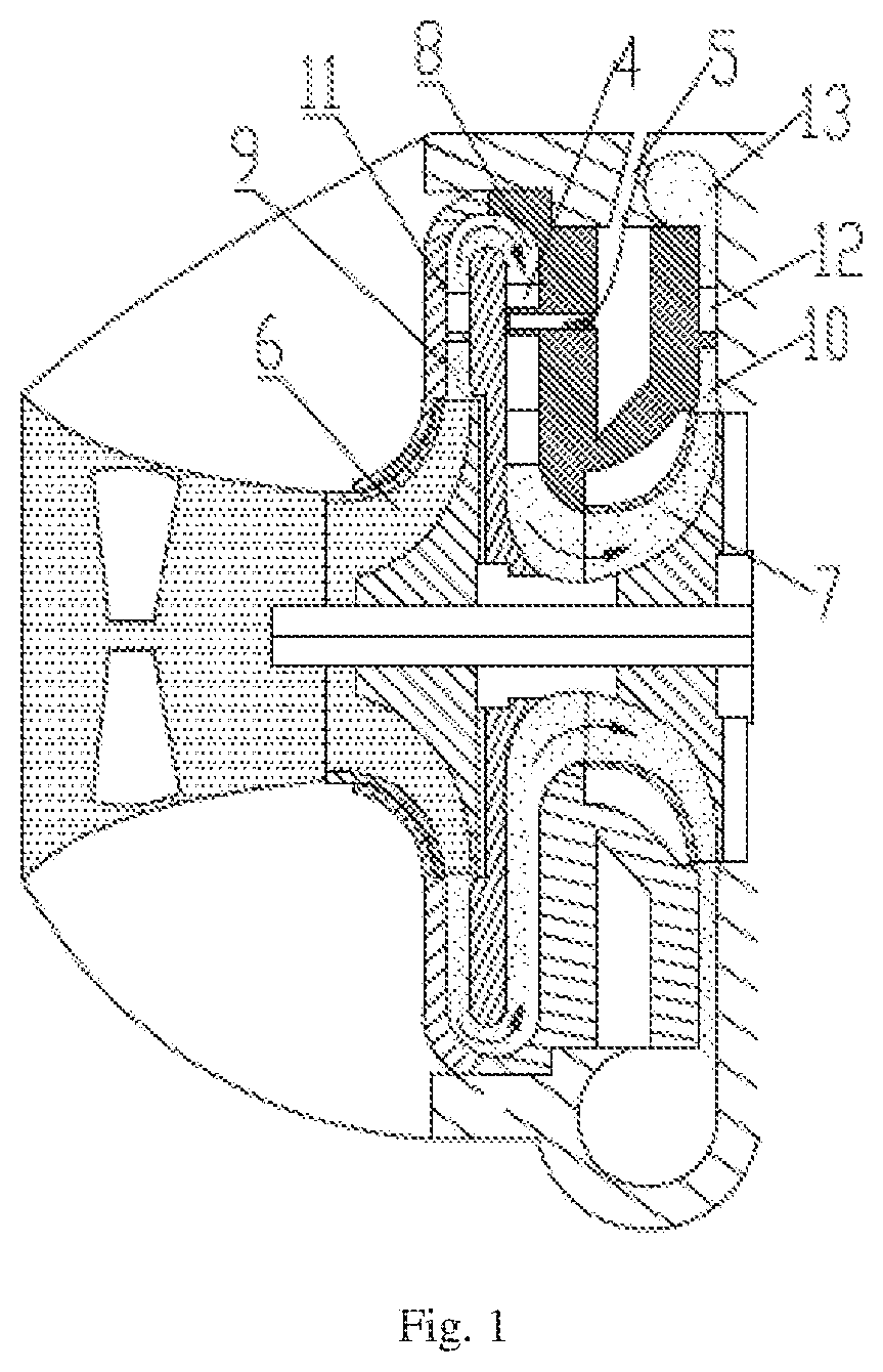
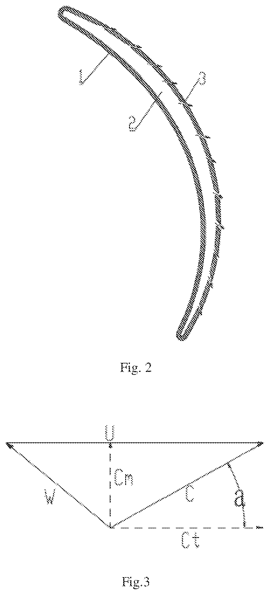
[0037]The embodiment of the present disclosure provides a reflux device blade, including: a blade main body 1, a hollow cavity 2 is formed in the blade main body 1, and an air supplement hole 3 is formed in the blade main body 1.

[0038]Referring to FIGS. 1 to 3, when the compressor is running at a design operating condition, after an air refrigerant passes through a first-stage impeller 6, since the refrigerant performs circular motion with the first-stage impeller 6, an absolute speed C of the airflow is composed of Cm and Ct. The refrigerant airflow enters a first-...


PUM


Abstract

Embodiments of the present disclosure describe a reflux device blade and a compressor. The reflux device blade includes a blade main body, a hollow cavity is formed in the blade main body, and an air supplement hole is formed in the blade main body. When the hollow reflux device blade is adopted, the supplemental air entering the hollow cavity of the reflux device blade through an air supplement channel forms jet flow on a suction surface of the reflux device blade to blow off a low-speed low-energy area formed on the suction surface, so as to reduce the airflow mixing loss, prevent the intake distortion of a second-stage impeller, and improve the operation range of the compressor.

Description

CROSS-REFERENCE TO RELATED APPLICATIONS[0001]This application is the United States national phase of International Application No. PCT / CN2017 / 118108 filed Dec. 22, 2017, and claims priority to Chinese Patent Application No. 201710331361.8 filed May 11, 2017, the disclosures of which are hereby incorporated by reference in their entirety.BACKGROUND OF THE INVENTION[0002]Field of the Invention[0003]The present disclosure relates to the field of compressors, and in particular to a reflux device blade, and a compressor.[0004]Description of Related Art[0005]In a centrifugal compressor, after air is compressed, the temperature rises sharply, therefore the specific volume of the air is large at a high temperature, and the energy consumption of the compressor is increased sharply under the condition of ensuring the same cooling capacity. In order to reduce the power consumption of the compressor and improve the refrigeration capacity, a multi-stage compression refrigeration cycle is commonl...

Claims


Application Information

Patent Timeline
Patent Type & Authority Patents(United States)
IPC IPC(8): F04D29/44F04D17/12F04D29/42F04D29/66F04D29/68
CPCF04D29/444F04D17/12F04D29/4206F04D29/667F04D29/684F05D2240/12F05D2240/124F04D1/06
Inventor LIU, ZENGYUEZHONG, RUIXINGJIANG, NANJIANG, CAIYUNCHEN, YUHUIZHOU, YILEI, LIANDONGOUYANG, XINWANG
Owner GREE ELECTRIC APPLIANCES WUHAN
Learn More