Electric fan

A technology for electric fans and components, applied in the field of electric fans, can solve the problems of sagging of the machine head assembly and the reduction of friction, and achieve the effects of preventing sagging, balancing gravity, and improving stability and reliability.

Active Publication Date: 2015-05-20
GREE ELECTRIC APPLIANCES INC OF ZHUHAI
View PDF6 Cites 6 Cited by
  • Summary
  • Abstract
  • Description
  • Claims
  • Application Information

AI Technical Summary

Problems solved by technology

[0005] An electric fan is provided in the embodiment of the present invention, which can effectively prevent the problem that the frictional force between the adjustment box and the fuselage assembly is reduced due to friction and wear, and the nose assembly sags.

Method used


Image

  • Electric fan
  • Electric fan
  • Electric fan

Examples


Embodiment Construction

[0023] The present invention will be described in further detail below in conjunction with the accompanying drawings and specific embodiments, but not as a limitation of the present invention.

[0024] In the present invention, the front, back, left, and right directions when the electric fan is working are the reference directions of the following embodiments.

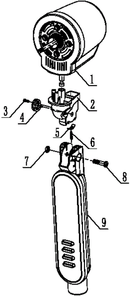
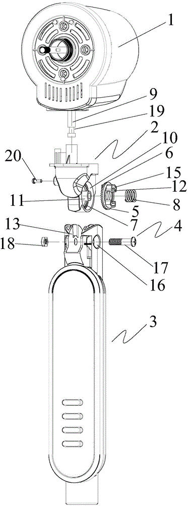
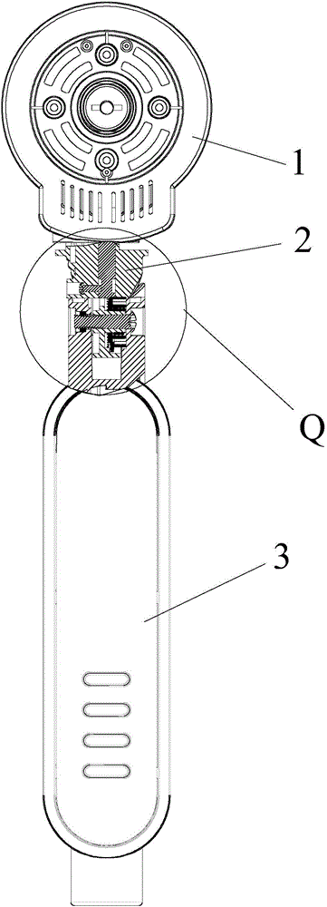
[0025] see Figure 2 to Figure 4 As shown, according to the embodiment of the present invention, the electric fan includes a head assembly 1, an adjustment box 2 and a fuselage assembly 3, the head assembly 1 is arranged on the adjustment box 2, and the adjustment box 2 is rotatably arranged on the horizontal shaft 4 On the fuselage component 3, the sliding sleeve on the horizontal rotating shaft 4 is provided with an adjusting gear 5, which is circumferentially fixed on the fuselage component 3, and the first end surface of the adjusting gear 5 is provided with a first protruding towards the adjusting box 2. The end...


PUM


Abstract

The invention discloses an electric fan. The electric fan comprises a fan head assembly, an adjusting box and a fan body assembly. The fan head assembly is arranged on the adjusting box. The adjusting box is arranged on the fan body assembly in the mode of rotating around a horizontal rotating shaft. The horizontal rotating shaft is sleeved with an adjusting gear in a sliding mode. The adjusting gear is fixed to the fan body assembly in the circumferential direction. The first end face of the adjusting gear is provided with first end face teeth extending towards the adjusting box. The adjusting box is provided with second end face teeth matched with the first end face teeth. An adjusting spring is arranged between the second end face of the adjusting gear and the fan body assembly. One end of the adjusting spring abuts against the first end face of the adjusting gear. The second end of the adjusting spring abuts against the fan body assembly. According to the electric fan, the problems that due to frictional wear, frictional force between the adjusting box and the fan body assembly is reduced, and the fan head assembly droops can be effectively prevented.

Description

technical field [0001] The invention relates to the field of electrical appliances, in particular to an electric fan. Background technique [0002] The main body of electric fans currently on the market is as attached figure 1 As shown, the head assembly 1 and the adjustment box 2 are connected in a limited position by screws 3, the head assembly 1 and the fuselage assembly 9 are assembled mainly through the adjustment box 2, the balance spring 4, the positioning piece 5 and the adjustment spring assembly 6, and then through The nut 7 and the bolt 8 are assembled and fixed to realize the adjustment of the up / down shaking head angle, and finally achieve the user's ideal air supply angle. [0003] One end of the two mounting feet of the balance spring 4 is assembled with the adjustment box 2, and the other end is staggered with a certain angle along the circumferential direction with the locking slot of the fuselage assembly 9, so as to ensure that sufficient torque can be ge...

Claims


Application Information

Patent Timeline
IPC IPC(8): F04D25/10F04D29/00F04D29/66
CPCF04D25/105F04D27/00F04D29/002
Inventor 王桃元
Owner GREE ELECTRIC APPLIANCES INC OF ZHUHAI
Why Eureka
Try Eureka