Check patentability & draft patents in minutes with Patsnap Eureka AI!

Deceleration device

A technology of reduction gear and reduction mechanism, applied in the direction of transmission, transmission parts, gear transmission, etc., can solve the problems of rising lubricant temperature and difficulty in cooling the reduction mechanism sufficiently, and achieve the effect of improving cooling performance

Active Publication Date: 2015-05-20
SUMITOMO HEAVY IND LTD
View PDF8 Cites 1 Cited by
  • Summary
  • Abstract
  • Description
  • Claims
  • Application Information

AI Technical Summary

Problems solved by technology

[0006] However, in the above reduction gear transmission, the temperature of the lubricant rises and it may be difficult to sufficiently cool the reduction mechanism.

Method used


Image

  • Deceleration device
  • Deceleration device
  • Deceleration device

Examples


Embodiment Construction

[0016] Hereinafter, an example of an embodiment of the present invention will be described in detail with reference to the drawings.

[0017] first reference figure 1 The overall structure of this reduction gear transmission will be described.

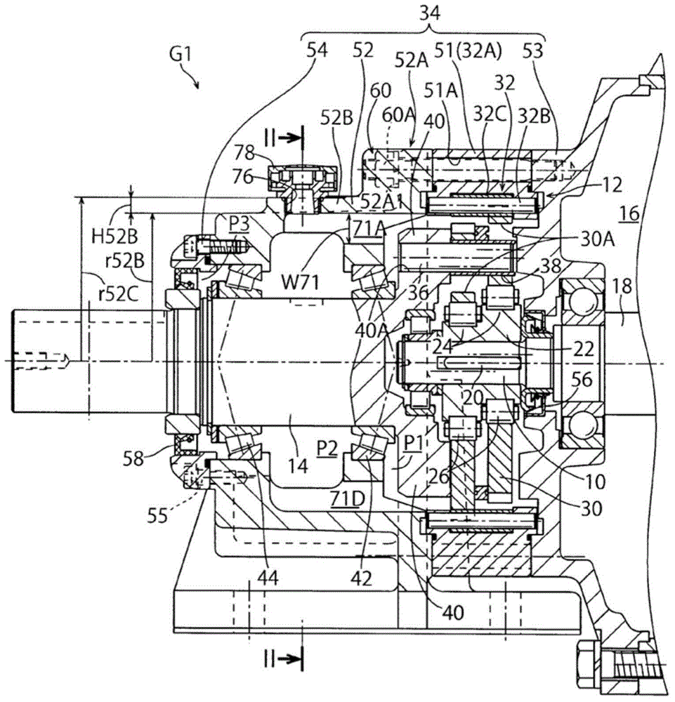
[0018] The reduction gear G1 includes an input shaft 10 , a reduction mechanism 12 , and an output shaft 14 that outputs a rotation decelerated by the reduction mechanism 12 . The reduction mechanism 12 is an eccentric oscillating planetary gear reduction mechanism called a center crank type.

[0019] The input shaft 10 of the reduction gear G1 is integrated with a motor shaft 18 of a motor (not shown in its entirety) 16 . The input shaft 10 is coupled to an eccentric body shaft 22 via a key 20 . Two eccentric bodies 24 are integrally formed on the eccentric body shaft 22 .

[0020] On the outer periphery of the eccentric body 24 , an external gear 30 is assembled so as to be swingable via rollers (eccentric body bearings) 26 . Th...


PUM


Abstract

The invention provides a deceleration device capable of using the lubricant in the deceleration device, and improving cooling performance of the deceleration device. The deceleration device comprises an output shaft, which can be used to output the decelerated rotation of the deceleration mechanism (12); a main body housing (51), which is used for accommodating the deceleration mechanism; an output housing (52), which can be used to accommodating the output shaft. The output housing is provided with a cylindrical part (52B), which is used to support the output shaft by a first bearing (42); and a connecting part (52A), which is extended along the radial outer side of the cylindrical part, and is connected with the main body housing. The load side end surface of the connecting part is provided with a connecting part (60) connected with the main body housing, and the position of the outer periphery of the cylindrical part avoiding the position of the lubricant is provided with a protruding part (52C). The radial inner side of the protruding part and the radial outer side of the bearing are provided with the lubricant channel (71), and the channel is communicated with the space (P1) closer to the deceleration device side than the bearing and the space (P2) closer to the load side than the bearing.

Description

[0001] This application claims priority based on Japanese Patent Application No. 2013-232602 filed on November 8, 2013. The entire contents of this Japanese application are incorporated herein by reference. technical field [0002] The invention relates to a reduction gear. Background technique [0003] For example, Patent Document 1 discloses a reduction gear transmission including an eccentric oscillating type reduction mechanism and an output shaft that outputs rotation decelerated by the reduction mechanism. The housing of the reduction gear transmission includes a main body housing that accommodates the reduction mechanism, and an output housing that accommodates the output shaft. [0004] Lubricant is enclosed in the casing of the reduction gear transmission, and the lubricant lubricates each sliding portion of the reduction mechanism and cools the reduction mechanism that generates heat. [0005] Patent Document 1: Japanese Unexamined Patent Publication No. 2004-211...

Claims


Application Information

Patent Timeline
Patent Type & Authority Applications(China)
IPC IPC(8): F16H57/04
CPCF16H57/02F16H57/0413F16H57/0424F16H1/34F16H57/042F16H2057/02073
Inventor 为永淳阿部瞬
Owner SUMITOMO HEAVY IND LTD
Features
  • R&D
  • Intellectual Property
  • Life Sciences
  • Materials
  • Tech Scout
  • Unparalleled Data Quality
  • Higher Quality Content
  • 60% Fewer Hallucinations
Learn More