
An electrical connection structure, assembly method, and lamp for an LED lamp board and a power board

A technology of LED light board and electrical connection structure, applied in the direction of light source, point light source, lighting device, etc., can solve the problems of low wire efficiency, wire aging, wire false welding, etc., to improve welding efficiency, facilitate welding, and improve quality Effect

Active Publication Date: 2018-09-18
ZHONGSHAN GLAMOR OPTOELECTRONICS TECH
View PDF8 Cites 0 Cited by
  • Summary
  • Abstract
  • Description
  • Claims
  • Application Information

AI Technical Summary

Problems solved by technology

[0003] In the prior art, in order to realize the power supply board to provide power for the LED light board, the electrical connection between the power board and the LED light board is generally realized through wires, but the connection method using wires often causes false welding or disconnection, etc., after long-term use The wire will be aging and short circuit will appear. Moreover, the connection method of the wire needs to cut the wire, peel off the insulation at both ends of the wire, and then solder the two ends of the wire to the power board and the LED light board respectively. Workers also need to carefully Clear the positive and negative poles of the power supply and the positive and negative poles of the LED light board, so the efficiency of the wire connection method is low

Method used


Image

  • An electrical connection structure, assembly method, and lamp for an LED lamp board and a power board
  • An electrical connection structure, assembly method, and lamp for an LED lamp board and a power board
  • An electrical connection structure, assembly method, and lamp for an LED lamp board and a power board

Examples


Embodiment 1

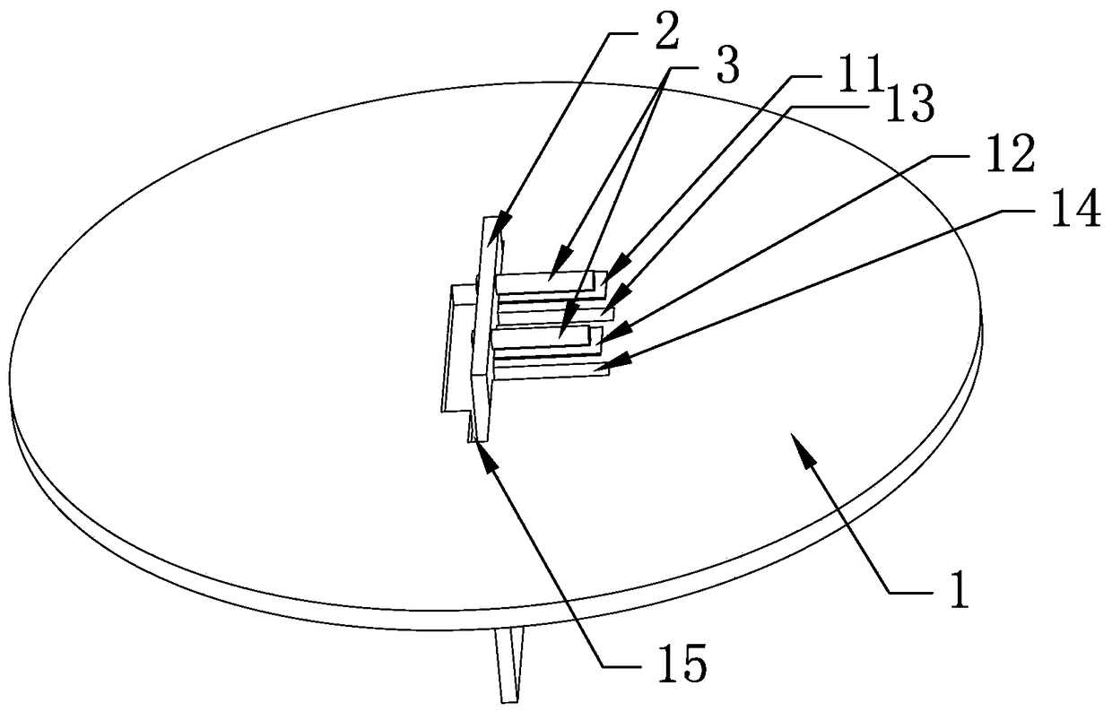
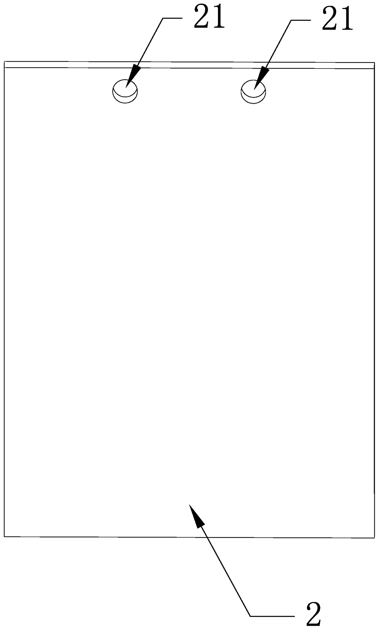
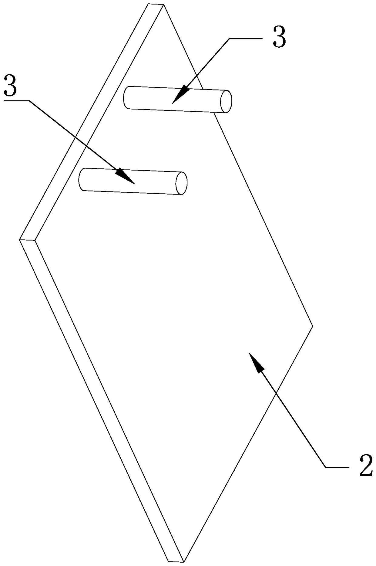
[0049] A kind of electrical connection structure of LED lamp board and power supply board of this embodiment, such as Figure 1 to Figure 4 As shown, it includes an LED lamp board 1 and a power board 2, and also includes two conductive pins 3; the LED lamp board 1 is provided with two patch pads for power supply input, and the power board 2 is provided with a power supply output Two soldering jacks 21, one end of the two conductive pins 3 are respectively welded to the two patch pads of the LED lamp board 1, and the other end of the two conductive pins 3 is connected to the power board 2 The two soldering jacks 21 are soldered.

[0050] This embodiment proposes for the first time that the electrical connection between the two circuit boards is completed through the combination of patch welding and plug-in welding. By using the conductive pin 3 to realize the electrical connection between the LED lamp board 1 and the power supply board 2, only the The two ends of the conductiv...

Embodiment 2

[0062] The electrical connection structure of an LED lamp board and a power board in this embodiment is different from the structure of Embodiment 1 in that: the LED lamp board is provided with two welding jacks for power supply input, and the power board is provided with The two patch pads for the output of the power supply, one end of the two conductive pins are respectively welded to the two welding sockets of the LED lamp board, and the other ends of the two conductive pins are connected to the two soldering holes of the power board. A patch pad soldering.

[0063] This structure is simpler and quicker when soldering conductive pins.

Embodiment 3

[0065] This embodiment provides an assembly method of the electrical connection structure of the LED lamp board and the power board of Embodiment 1, which includes the following steps for the case where the power board is vertically installed on the LED lamp board:

[0066] Step 1: Solder one end of the two conductive pins 3 to the two welding jacks 21 of the power board 2 respectively;

[0067] Step 2: Put the other ends of the two conductive pins 3 in Step 1 from the back of the LED light board 1 to the front (the front refers to the side of the LED light board 1 with LED lamp beads) from the first through hole 13 and the second through hole 13 respectively. The two through holes 14 pass through the LED lamp board 1, and the two conductive pins 3 are moved sideways to the first pad 11 and the second pad 12;

[0068] Step 3: Solder the other ends of the two conductive pins 3 to the first pad 11 and the second pad 12 .

[0069] In this embodiment, the two conductive pins 3 we...


PUM


Abstract

The invention relates to the technical field of LED lamps, in particular to an electric connecting structure and assembling method of an LED lamp panel and a power panel and a lamp. The electric connecting structure comprises the LED lamp panel, the power panel and two conduction needles, wherein the LED lamp panel is provided with two welding inserting holes for power input, the power panel is provided with two patch welding discs for power output, one ends of the two conduction needles are welded to the two welding inserting holes of the LED lamp panel, and the other ends of the two conduction needles are welded to the two patch welding discs of the power panel. According to the assembling method, one ends of the two conduction needles are welded to the two welding inserting holes of the power panel respectively, then the other ends of the two conduction needles penetrate through the LED lamp panel from the back surface to the obverse surface of the LED lamp panel through a first through hole and a second through hole, and the two conduction needles are laterally transferred to the first welding disc and the second welding disc; finally, the other ends of the two conduction needles are welded to the first welding disc and the second welding disc. The lamp comprises an outer shell, wherein the electric connecting structure of the LED panel and the power panel is arranged in the outer shell.

Description

technical field [0001] The invention relates to the technical field of LED lamps, in particular to an electrical connection structure of an LED lamp board and a power board, an assembly method and a lamp. Background technique [0002] The circuit board of the LED lamp generally includes an LED lamp board and a power board, the LED lamp board is used to fix the LED lamp, and the power board is used to provide power for the LED lamps on the LED lamp board. [0003] In the prior art, in order to realize the power supply board to provide power for the LED light board, the electrical connection between the power board and the LED light board is generally realized through wires, but the connection method using wires often causes false welding or disconnection, etc., after long-term use The wire will be aging and short circuit will appear. Moreover, the connection method of the wire needs to cut the wire, peel off the insulation at both ends of the wire, and then solder the two end...

Claims


Application Information

Patent Timeline
Patent Type & Authority Patents(China)
IPC IPC(8): F21V23/06F21Y115/10
CPCF21V23/06F21Y2101/00
Inventor 刘天明沈仁春李军肖虎张沛涂梅仙
Owner ZHONGSHAN GLAMOR OPTOELECTRONICS TECH
Learn More