Automobile powertrain suspension arm destructive force test fixture and tensile test device

A technology of automobile powertrain and cantilever arm, applied in measuring devices, instruments, scientific instruments, etc., can solve the problems of inaccurate test results, inaccurate destructive force, damage to tensile test devices, etc., and achieve accurate test data. believable effect

Inactive Publication Date: 2017-05-31
SAIC MOTOR
View PDF5 Cites 0 Cited by
  • Summary
  • Abstract
  • Description
  • Claims
  • Application Information

AI Technical Summary

Problems solved by technology

like image 3 As shown, the bending moment M1 can cause the failure mode of the test part to be inconsistent with the vehicle test, and the interference of M1 leads to inaccurate destructive force measured in the test. It has been proved through a large number of tests that this fixture design causes the error of the test data to exceed 20%. above
At the same time, since the bending moment M2 acts on the guide rod, it may damage the tensile test device when it is severe
[0005] The destructive force test of the support arm is of great significance for evaluating the strength of the support, ensuring the safety of the vehicle, checking the design quality, and optimizing the design. lead to damage to experimental equipment, so it is urgent to study and solve the above problems

Method used


Image

  • Automobile powertrain suspension arm destructive force test fixture and tensile test device
  • Automobile powertrain suspension arm destructive force test fixture and tensile test device
  • Automobile powertrain suspension arm destructive force test fixture and tensile test device

Examples


Embodiment Construction

[0032] It should be noted that the principles, features and advantages of the automobile powertrain suspension arm destructive force test fixture and tensile test device of the present invention will be specifically described below by way of example, but all descriptions are only for illustration , but they should not be construed as forming any limitations on the present invention. In addition, any single technical feature described or implied in each embodiment mentioned herein, or any single technical feature shown or implied in each drawing, can still be included in these technical features (or their equivalents) Objects) continue to make any combination or deletion, so as to obtain more other embodiments of the present invention that may not be directly mentioned herein.

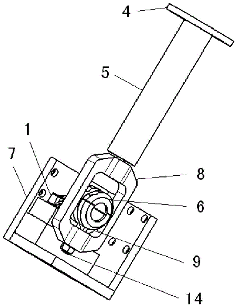
[0033] Please refer to Figure 4 As shown, a specific example of the destructive force test fixture of the suspension arm of the automobile powertrain suspension of the present invention is provided in...


PUM


Abstract

The invention relates to an automatic force assembly suspended supporting arm destructive force test clamp and a tensile test device. The test clamp comprises a connecting flange, a force guide rod, a force guide framework, a fixed clamp ring and a mounting base, wherein the connecting flange is fixedly connected to a motion part of a tensile test device for a automatic force assembly suspended supporting arm destructive force test; the force guide rod is in a shape of a rod and provided with a first end and a second end, and the first end is fixedly connected with the connecting flange; the force guide framework is provided with a first end and a second end, the first end of the force guide framework is connected with the second end of the force guide rod, and a top pin is arranged on the second end of the force guide frame; the fixed clamp ring is arranged in the force guide framework, and comprises an upper sheet and a lower sheet which can be assembled and disassembled so as to clamp and fix one end of an automatic force assembly suspended supporting arm, wherein a guide channel is arranged on the lower sheet, and the guide channel and the top pin are in point contact fit, so as to form a pin transfer structure which can do rotating motion around the contact point during the force transferring process so as to prevent bending moment caused by overconstraint. The test clamp can be applied to the various automatic force assembly suspended supporting arm destructive force bench tests.

Description

technical field [0001] The invention relates to a test jig, in particular to a destructive force test jig and a tensile test device for suspension parts of an automobile power assembly. Background technique [0002] The suspension system of the automobile powertrain is one of the most important safety components of the automobile. Its main function is to fix the engine and gearbox, and connect the engine and gearbox to the body and frame through the suspension bracket or support arm. Thus, the suspension arm bears on the one hand the loads generated by the engine drive torque and at the same time the loads generated by the excitation of the road loads. The harsh load environment of the suspension arm requires its high strength. An important test to evaluate the strength of the arm is the arm destructive force test. figure 1 Shown is a suspension arm 1a of an engine in the prior art, one end of the arm is connected to the engine through a bolt hole 2a, and the other end is c...

Claims


Application Information

Patent Timeline
Patent Type & Authority Patents(China)
IPC IPC(8): G01N3/04
Inventor 孙明孙威韩愈琪徐峰康燕万枫
Owner SAIC MOTOR
Why Eureka
Try Eureka