End mill

An end mill and blade technology, applied in the field of end mills, can solve the problems of over-constraint, excessive space size constraints, unfavorable blade installation, etc., and achieve the effects of reducing manufacturing difficulty, easily limiting accuracy, and avoiding over-constraint phenomena.

Active Publication Date: 2020-10-09
KYOCERA CORP
View PDF8 Cites 0 Cited by
  • Summary
  • Abstract
  • Description
  • Claims
  • Application Information

AI Technical Summary

Problems solved by technology

Moreover, in the above-mentioned way of connecting the blade and the screw, there are too many constraints on the space size, which is easy to form an over-constraint phenomenon, which is not conducive to the installation of the blade

Method used


Image

  • End mill
  • End mill
  • End mill

Examples


Embodiment Construction

[0041] Typical embodiments that embody the features and advantages of the present invention will be described in detail in the following description. It should be understood that the present invention is capable of various changes in different embodiments without departing from the scope of the present invention, and that the description and illustrations therein are illustrative in nature and not limiting. this invention.

[0042] The present disclosure provides an end mill. End mills can be flat end mills, round nose end mills, etc. The types of end mills are not limited here. Specifically, in this application, end mills are described using ball end mills as an example, and others will not be described in detail. .

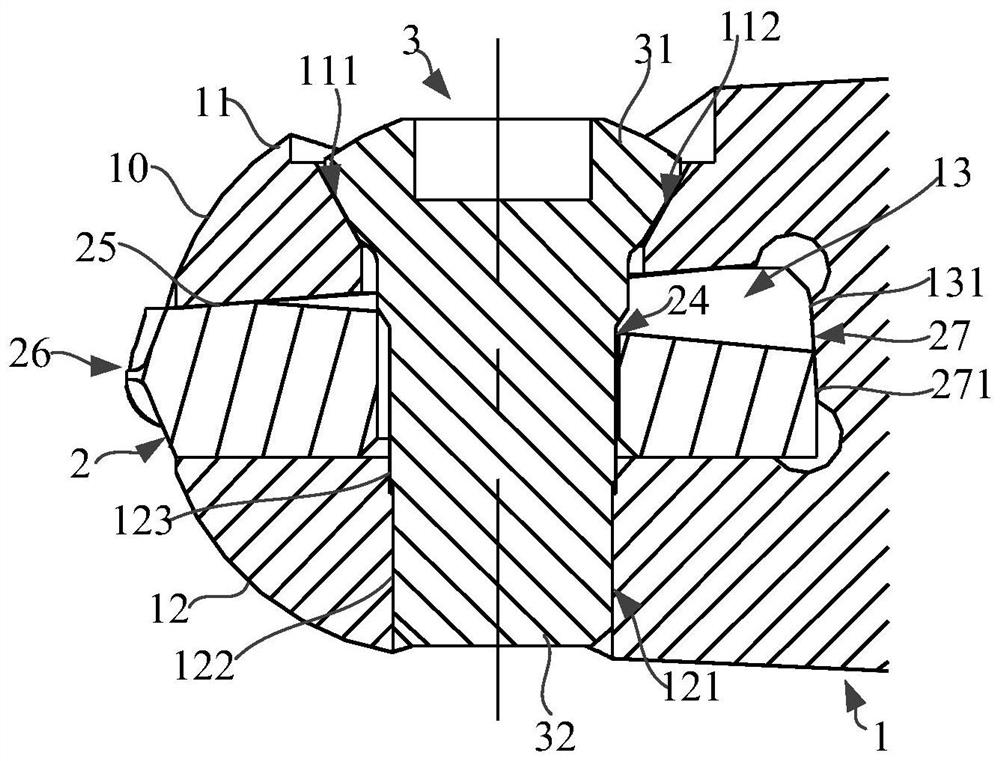
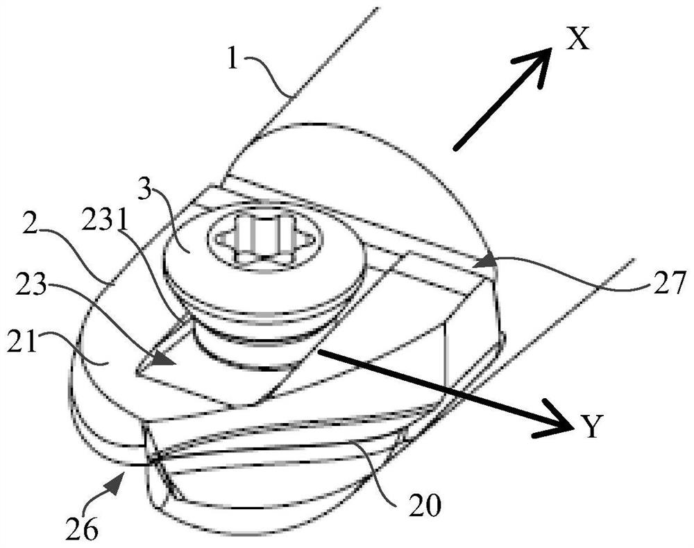
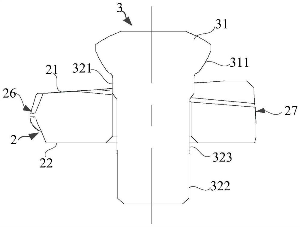
[0043] see figure 1 , The end mill of this embodiment is a rod extending from front to rear along the rotation axis. The rod rotates around its central axis, so the central axis of the rod is the axis of rotation of the end mill. Wherein, the position where...


PUM


Abstract

The invention provides an end mill. The end mill comprises a mill handle, a blade and a fastener. A mounting base is arranged at the front end of the mill handle. The mounting base comprises clampingarms arranged oppositely. A narrow slit is formed between the two clamping arms. First inclined surfaces are arranged on the inner side surfaces of the clamping arms correspondingly. The blade is arranged in the narrow slit in a clamped mode. Second inclined surfaces are arranged on abutting surfaces of the blade correspondingly. A limit groove is formed in one abutting surface in the direction ofa rotary axis of the blade and extends from front to back. The limit groove comprises two oppositely-arranged wall surfaces and a bottom surface connected with the two wall surfaces. A through hole is formed in the bottom surface of the limit groove. The two wall surfaces are provided with constraint surfaces correspondingly. The fastener penetrates through the through hole from a mounting hole,and a fixing hole is connected with the mounting base, so that the blade is detachably arranged on the mounting base. The two constraint surfaces are used for clamping tightly a column. According to the end mill provided by the invention, an over-constrained phenomenon can be avoided, and the manufacturing difficulty is lowered.

Description

technical field [0001] The present invention relates to an end mill used in cutting. Background technique [0002] At present, the fixed installation of the blade of the ball end mill is all through the installation screw, or the combination of the installation screw and the "V" shape constraint surface of the blade, to install the blade on the surface of the tool handle mounting seat. By ensuring the accuracy of the center hole of the blade, or the accuracy of the center hole and the "V"-shaped surface, the coaxial accuracy of the installation of the blade and the handle is guaranteed. [0003] Patent Document 1: JPWO2017094531A1. [0004] This patent document 1 introduces an indexable insert type cutting tool in which the insert is fixed by a mounting screw. When the insert and the screw are assembled, in the axial direction of the ball end mill, the screw needs to contact the upper jaw and the lower jaw of the handle, and at the same time contact the inner wall of the c...

Claims


Application Information

Patent Timeline
Patent Type & Authority Applications(China)
IPC IPC(8): B23C5/22B23C5/10
CPCB23C5/2208B23C5/1027
Inventor 刘东亨
Owner KYOCERA CORP
Why Eureka
Try Eureka