A Method for Analyzing Contact Stress of Revolving Pair with Clearance

A contact stress and rotating pair technology, applied in constraint-based CAD, instrument, geometric CAD, etc., can solve problems such as limited number of nodes, system equation constraints, contact boundary stress fluctuations, etc., to avoid over-constrained problems and improve calculation accuracy. , the effect of reducing the fluctuation of contact stress

Active Publication Date: 2021-05-04
HUAZHONG UNIV OF SCI & TECH
View PDF3 Cites 0 Cited by
  • Summary
  • Abstract
  • Description
  • Claims
  • Application Information

AI Technical Summary

Problems solved by technology

From the perspective of imposing contact constraints, too few integration points are likely to cause missed contact detection, and the integration accuracy cannot be guaranteed. Therefore, it is generally necessary to arrange multiple numerical integration points
However, due to the limited number of nodes after the finite element discretization of the contact boundary, too many integration points will lead to over-constraint of the system equations, which will cause stress fluctuations at the contact boundary and affect the accuracy of numerical analysis

Method used


Image

  • A Method for Analyzing Contact Stress of Revolving Pair with Clearance
  • A Method for Analyzing Contact Stress of Revolving Pair with Clearance
  • A Method for Analyzing Contact Stress of Revolving Pair with Clearance

Examples


Embodiment Construction

[0049]The present invention will be further described below with reference to the accompanying drawings and specific examples.

[0050]The present invention is to be set forth is a calculation method for reducing contact stress fluctuations caused by a numerical integral point over-aid finger in a gap rotation sub-contact finite element analysis.

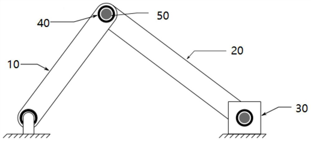
[0051]The crank slider mechanism is extremely common in the mechanical system, such as the piston link mechanism of the engine.figure 1 A schematic diagram of the crank slider mechanism of the present embodiment. The crank slider mechanism includes a crank 10, a link 20, a slider 30, a bearing 40, and a rotating shaft 50. Crank 10 two spin spacing 1.2m, width 0.2m. The connecting rod 20 has two spin spacing 1.6m, and the width is 0.3m. The slider 30 long width is 0.3m. The inner diameter of the bearing 40 is 0.06m. The shaft 50 has a diameter of 0.057 mm. All components have a density of 7800kg / m?3. The elastic modulus of the rotating shaft 5...


PUM


Abstract

The invention relates to a method for improving the calculation accuracy of contact stress in the finite element analysis of a gap rotating pair. For the finite element model of the clearance rotating pair, the meshing of the contact boundary is carried out, and the numerical integration points are set at the contact boundary of the bearing. The projection point and its parameter coordinates of each numerical integration point on the contact boundary of the rotating shaft are searched, and the normal distance and geometric measure at the projection point are calculated. After completing the search of all projected points and the calculation of related variables, the parameter coordinates of the equivalent projected points, normal distance, geometric measure, normal and tangential traction are calculated for each node of the bearing contact boundary. After the cycle completes the calculation of the equivalent variables of all nodes, the contact force virtual work integral is calculated and submitted to the system equation. This method can eliminate the over-constraint of the system caused by the increase of the number of integration points, and reduce the fluctuation of the contact stress in the rotating pair of gaps.

Description

Technical field[0001]The present invention relates to computer auxiliary engineering analysis, and more particularly to a method for simulating a gap rotating sub-contact stress in finite element analysis, which is used for time propulsion engineering simulation to assist users in improvement. Engineering products (for example, cars, aircraft) are designed to make decisions.Background technique[0002]Due to factors such as design, manufacturing, processing, wear, the rotational deposit in mechanical systems (e.g., cars, aircraft, machine, machine, robot) can inevitably exist. The gap causes the bearing and the shaft frequent contact collision during the relative exercise, introduce vibration, noise, wear, etc. in the system, which seriously affects the operating accuracy of the system and shorten the service life. Therefore, analyzing the dynamics response of the agencies containing the gap motility has important academic significance and economic value.[0003]Finite element methods a...

Claims


Application Information

Patent Timeline
Patent Type & Authority Patents(China)
IPC IPC(8): G06F30/23G06F30/17G06F111/10G06F111/04G06F119/14
Inventor 皮霆张云清马冀吕天启
Owner HUAZHONG UNIV OF SCI & TECH
Why Eureka
Try Eureka