A method for analyzing contact stress of a clearance revolute pair

A contact stress and revolving pair technology, applied in special data processing applications, instruments, calculations, etc., can solve problems such as limited number of nodes, system equation constraints, contact boundary stress fluctuations, etc., to avoid over-constraint problems, improve calculation accuracy, Effect of reducing contact stress fluctuations

Active Publication Date: 2019-06-18
HUAZHONG UNIV OF SCI & TECH
View PDF3 Cites 2 Cited by
  • Summary
  • Abstract
  • Description
  • Claims
  • Application Information

AI Technical Summary

Problems solved by technology

From the perspective of imposing contact constraints, too few integration points are likely to cause missed contact detection, and the integration accuracy cannot be guaranteed. Therefore, it is generally necessary to arrange multiple numerical integration points
However, due to the limited number of nodes after the finite element discretization of the contact boundary, too many integration points will lead to over-constraint of the system equations, which will cause stress fluctuations at the contact boundary and affect the accuracy of numerical analysis

Method used


Image

  • A method for analyzing contact stress of a clearance revolute pair
  • A method for analyzing contact stress of a clearance revolute pair
  • A method for analyzing contact stress of a clearance revolute pair

Examples


Embodiment Construction

[0049] The present invention will be further described below in conjunction with the accompanying drawings and specific embodiments.

[0050] What the present invention intends to elaborate is a calculation method for reducing contact stress fluctuation caused by over-constraint of numerical integral points in the contact finite element analysis of gap revolving pair.

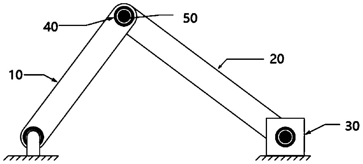
[0051] The slider-crank mechanism is very common in mechanical systems, such as the piston-and-rod mechanism of an engine. figure 1 It is a schematic diagram of the slider crank mechanism of this embodiment. The slider crank mechanism includes a crank 10 , a connecting rod 20 , a slider 30 , a bearing 40 and a rotating shaft 50 . The distance between two rotating shafts of the crank 10 is 1.2m, and the width is 0.2m. The distance between the two rotating shafts of the connecting rod 20 is 1.6m, and the width is 0.3m. Slide block 30 length and width are 0.3m. The inner diameter of the bearing 40 is 0.06m. T...


PUM


Abstract

The invention relates to a method for improving contact stress calculation precision in finite element analysis of a clearance revolute pair. The method comprises steps of for the clearance revolute pair finite element model, performing mesh generation on the contact boundary, and setting numerical integration points at the bearing contact boundary; searching the projection point of each numericalintegration point on the contact boundary of the rotating shaft and the parameter coordinates of the projection point, and calculating the normal spacing and the geometric measurement of the projection point; and after searching of all projection points and calculation of related variables are circularly completed, calculating equivalent projection point parameter coordinates, normal spacing, geometric measurement, normal traction force and tangential traction force for each node of the bearing contact boundary; and after the calculation of the equivalent variables of all the nodes is circularly completed, calculating a contact force virtual power integral, and submitting a system equation. The method can eliminate system over-constraint caused by increase of the number of integration points, and reduces fluctuation of contact stress in a clearance revolute pair.

Description

technical field [0001] The present invention relates to computer-aided engineering analysis, and more particularly, to a method for simulating the contact stress of a revolving pair of clearances in a finite element analysis for time-advancing engineering simulations to assist users in improving Decisions are made during the design of engineering products (e.g., automobiles, airplanes). Background technique [0002] Due to factors such as design, manufacturing, processing, wear, etc., there are inevitably gaps in the rotating joints in mechanical systems (eg, automobiles, aircrafts, machine tools, robots). The gap makes the bearing and the rotating shaft frequently contact and collide during the relative movement, and introduces vibration, noise, wear and other phenomena into the system, which seriously affects the operating accuracy of the system and shortens the life of the system. Therefore, it is of great academic significance and economic value to analyze and calculate...

Claims


Application Information

Patent Timeline
Patent Type & Authority Applications(China)
IPC IPC(8): G06F17/50
Inventor 皮霆张云清马冀吕天启
Owner HUAZHONG UNIV OF SCI & TECH
Why Eureka
Try Eureka