Switching circuit applied to contact resistance testing equipment of electromagnetic relay

A technology for electromagnetic relays and testing equipment, applied in the direction of measuring resistance/reactance/impedance, instruments, measuring devices, etc., can solve the problems of high cost, unguaranteed reliability, occupying a large area of ​​PCB board, etc., to reduce the cost of instruments, improve The effect of measuring instrument performance and improving measurement reliability

Active Publication Date: 2015-05-20
HEFEI UNIV OF TECH
View PDF6 Cites 4 Cited by
  • Summary
  • Abstract
  • Description
  • Claims
  • Application Information

AI Technical Summary

Problems solved by technology

Since the electromagnetic relay has many contacts to be tested, a large number of switching relays are required, which will still occupy a large area of ​​PCB or require external relays. The closing time and other performance of the relays will gradually deteriorate with the number of times of us

Method used


Image

  • Switching circuit applied to contact resistance testing equipment of electromagnetic relay
  • Switching circuit applied to contact resistance testing equipment of electromagnetic relay
  • Switching circuit applied to contact resistance testing equipment of electromagnetic relay

Examples


Embodiment Construction

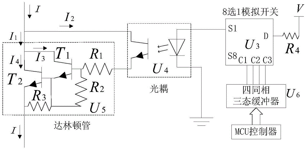
[0022] see image 3 and Figure 4 , the structural form of the switch circuit applied in the electromagnetic relay contact resistance testing equipment in the present embodiment is: set the contact switching switch control circuit to include constant current source, four in-phase three-state buffer U6, the first 8 select 1 analog switch U3 , and a gating circuit composed of multi-routing optocoupler U4 and Darlington tube U5; in this embodiment, the constant current source is made of Figure 4 The shown constant voltage source and constant current control are composed of two parts. The positive end of the constant voltage source is connected to the constant current control part through the load, and the other end of the constant current control part is directly connected to the negative end of the constant voltage source.

[0023] The four in-phase three-state buffer U6 has its input connected to the IO port of the MCU controller, and its output connected to the control termi...


PUM


Abstract

The invention discloses a switching circuit applied to contact resistance testing equipment of an electromagnetic relay. The switching circuit is characterized in that a contact changeover switching control circuit comprises a constant current source, a quadric-in-phase tristate buffer, a one-out-of-eight analog switch and a plurality of gating circuits consisting of optocouplers and Darlington transistors; the input end of the quadric-in-phase tristate buffer is connected with an IO (Input/Output) port of an MCU (Microprogrammed Control Unit), and the output end of the quadric-in-phase tristate buffer is connected with the control end of the one-out-of-eight analog switch; the input end of the one-out-of-eight analog switch is connected with a power supply, and eight output ends of the one-out-of-eight analog switch are respectively connected with the positive input end of the driving end of the optocoupler in one corresponding gating circuit; the negative end of the driving end of the optocoupler in one corresponding gating circuit is grounded; an output end collector of the one corresponding gating circuit is connected with a relay contact to be tested, and an output end emitter of the one corresponding gating circuit is connected with a control end of a Darlington transistor in one corresponding gating circuit; the input end of the Darlington transistor in one corresponding gating circuit is connected with a movable and static combination point of the electromagnetic relay to be tested; the GND end of the Darlington transistor of the corresponding gating circuit is connected with the negative end of the constant current source. According to the switching circuit disclosed by the invention, the contact resistance measurement reliability of the electromagnetic relay can be effectively improved.

Description

technical field [0001] The invention relates to a switching tube in electromagnetic relay testing equipment, in particular to a switching tube in multi-contact electromagnetic relay contact resistance testing equipment. Background technique [0002] Electromagnetic relay contacts undertake the task of switching current or carrying current for a long time, and its contact reliability is very important. In the parameter testing equipment of electromagnetic relays, the measurement of contact resistance is an indispensable testing item. Regarding the measurement of the contact resistance of electromagnetic relays, the national military standard GJB65B-99 requires the use of the Kelvin four-wire detection method. For this measurement method, a constant current source circuit and a contact resistance measurement circuit need to be provided during the measurement process. Electromagnetic relays usually have multiple contacts. The contact resistance of each contact needs to be measu...

Claims


Application Information

Patent Timeline
IPC IPC(8): G01R27/02
Inventor 胡社教魏星刚刘勤勤牛朝江萍郭强罗盛
Owner HEFEI UNIV OF TECH
Why Eureka
Try Eureka