Check patentability & draft patents in minutes with Patsnap Eureka AI!

Arc-free matrix intelligent bridge strong control high voltage circuit breaker

A high-voltage circuit breaker and arc-free technology, which is applied to circuit breaker components, circuits, high-voltage/high-current switches, etc., can solve problems such as inability to replace mechanical switches, inability to replace power circuit breakers, and potential safety hazards caused by thermal hazards. Achieve the effect of promoting R & D and production, breaking through the serious threat of arc, and simplifying the control and protection circuit

Active Publication Date: 2018-04-20
孙毅彪
View PDF4 Cites 0 Cited by
  • Summary
  • Abstract
  • Description
  • Claims
  • Application Information

AI Technical Summary

Problems solved by technology

However, in practice, it is found that high-power power electronic modules carry load current for a long time to generate large power consumption, and their unavoidable thermal hidden dangers bring greater risks and hidden dangers to system safety, so they cannot replace mechanical switches, let alone medium , High voltage power circuit breaker
[0007] For more than 100 years since the birth of power circuit breakers, experts in product research and development have always focused on the subject of arc extinction and struggled to solve key problems; and since the birth of power electronics technology for decades, experts in product research and development have always focused on high efficiency, high speed and low heat. , no one cared about the change of the basic structure and basic mode of the circuit breaker, and no one introduced a high-power circuit breaker solution that can avoid the switch arc and avoid the risk of online heat loss

Method used


Image

  • Arc-free matrix intelligent bridge strong control high voltage circuit breaker
  • Arc-free matrix intelligent bridge strong control high voltage circuit breaker
  • Arc-free matrix intelligent bridge strong control high voltage circuit breaker

Examples


Embodiment Construction

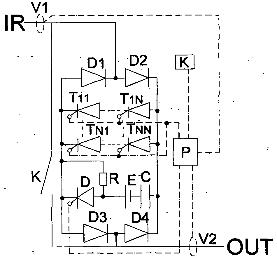
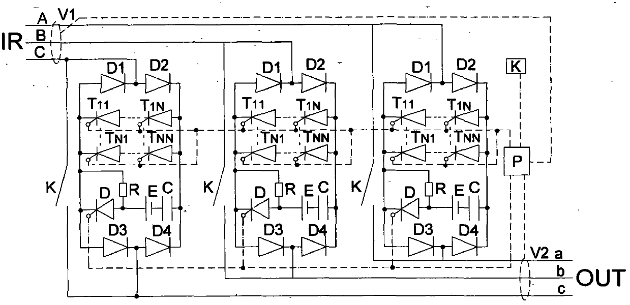
[0017] Such as figure 1 , as shown in 2, the arc-free amplified bridge high-voltage power circuit breaker is composed of a mechanical switch K, a bridge switch and its strong control circuit, a controller P, and monitoring instruments V1 and V2. After the main contacts of the bridge switch and K are connected in parallel Connected between power input (IR) and power output (OUT).

[0018] According to the connection mode and quantity of the main switching tube in the bridge switch, the non-contact channel of the arc-free intelligent bridge high voltage circuit breaker is divided into intelligent bridge type, parallel intelligent bridge type, series intelligent bridge type, matrix intelligent bridge type, There are eight forms of smart bridge strong control, parallel smart bridge strong control, series smart bridge strong control and matrix smart bridge strong control, collectively referred to as "bridge switch". This patent describes the matrix smart bridge strong control , it...


PUM


Abstract

The invention provides an arc-free matrix intelligent bridge strong control type high-voltage circuit breaker. The high-voltage circuit breaker comprises a mechanical switch K, a bridge switch, a strong control circuit, a controller P, and input-output monitoring instruments V1 and V2, wherein the bridge switch comprises diodes D1, D2, D3 and D4 and M rows (M is larger than or equal to 2) and N columns (N is larger than or equal to 2) non-contact switch matrixes; an inlet end (a positive pole of D2) and a K contact inlet end are jointly connected to a power supply input (IR) end; an outlet end (a positive pole of D4) and a K contact outlet end are jointly connected to a power supply output (OUT) end; the strong control circuit comprises a capacitor C, a voltage source E, a resistor R and a non-contact switch D; a control wire of P is connected with control electrodes of the matrixes and an actuating coil or a driving device of K; a signal wire is connected with V1 and V2; K contacts are firstly switched off and the bridge switch is subsequently switched off during opening; the bridge switch is firstly switched on and the K contacts are subsequently switched on during closing. The circuit breaker is used for replacing the existing high-voltage circuit breaker, so that the problem of the arc of the high-voltage circuit breaker is thoroughly eliminated.

Description

technical field [0001] The invention mainly relates to the field of high-voltage electric power, in particular to a high-voltage circuit breaker with a voltage level above 3KV. Background technique [0002] Historically, the key to why all kinds of high-power circuit breakers installed in the power supply and distribution equipment of the power system can connect or disconnect various load circuits according to people's will, especially to reliably disconnect short-circuit fault circuits It lies in the arc extinguishing function of the circuit breaker arc extinguishing system. [0003] As we all know, when operating a non-no-load circuit, the movable contact and the static contact of the circuit breaker will form a strong electric field at the rated voltage due to the small distance before the connection or the moment after the disconnection, causing medium or air ionization shock. wear, thereby generating an arc between the moving and static contacts. The greater the oper...

Claims


Application Information

Patent Timeline
Patent Type & Authority Patents(China)
IPC IPC(8): H01H73/18
CPCH01H33/04H01H33/59
Inventor 刘娜孙毅彪
Owner 孙毅彪
Features
  • R&D
  • Intellectual Property
  • Life Sciences
  • Materials
  • Tech Scout
  • Unparalleled Data Quality
  • Higher Quality Content
  • 60% Fewer Hallucinations
Learn More