Inductive coupling type equally-spaced bending dipole RFID (Radio Frequency Identification) tag antenna

An RFID tag and inductive coupling technology, applied in the field of microwave communication, can solve the problems of high cost of antenna production, difficult matching between antenna and chip, etc., and achieve the effects of easy matching, flexible and adjustable characteristic impedance, and easy impedance.

Inactive Publication Date: 2015-05-20
CENT SOUTH UNIV
View PDF3 Cites 14 Cited by
  • Summary
  • Abstract
  • Description
  • Claims
  • Application Information

AI Technical Summary

Problems solved by technology

[0003] The purpose of the present invention is to provide an inductive coupling type equidistant bent dipole RFID tag antenna, which solves the problems of high manufacturing cost of the current RFID tag antenna and difficult matching between the antenna and the chip

Method used


Image

  • Inductive coupling type equally-spaced bending dipole RFID (Radio Frequency Identification) tag antenna
  • Inductive coupling type equally-spaced bending dipole RFID (Radio Frequency Identification) tag antenna
  • Inductive coupling type equally-spaced bending dipole RFID (Radio Frequency Identification) tag antenna

Examples


Embodiment 1

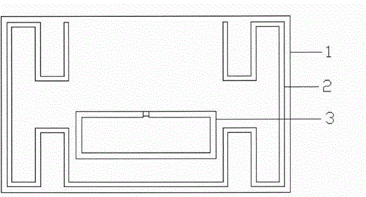
[0024] Embodiment 1: When the number of bending times is 2, the Higgs-3 chip of Alien Company is used, and its impedance changes with the frequency. At 920MHz, its impedance test value is about 27-j200Ω, and the antenna is designed at this frequency .

[0025] The schematic diagram of the antenna structure is as figure 1 As shown, its parameters after optimization are shown in Table 1, unit: mm.

[0026] Table 1

[0027] L 1

L 2

L 3

s

RL

RW

d

W 1

W 2

d 1

h

13.2

10

4

8

24

8

4

1

1

1

0.8

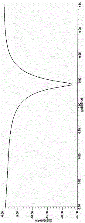
[0028] The final optimized antenna size is 49.2mm×30mm×0.8mm, the antenna impedance Z=23.12+j198.59Ω, which can realize the conjugate matching between the antenna impedance and the chip impedance, the reflection coefficient is -24.1dB, and the antenna gain is 1.35dB.

[0029] Such as image 3 The 3dB bandwidth shown is 886-940MHz, and the 10dB bandwidth is 910-926MHz, covering the 920-925M...

Embodiment 2

[0031] Embodiment 2: When the number of bending times is 4, the Higgs-3 chip of Alien Company is used, and its impedance changes with the frequency. At 920MHz, its impedance test value is about 27-j200Ω, and the antenna is designed at this frequency .

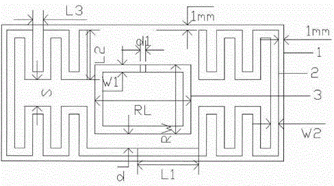
[0032] The schematic diagram of the antenna structure is as figure 2 As shown, its parameters after optimization are shown in Table 2, unit: mm.

[0033] Table 2

[0034] L 1

L 2

L 3

s

RL

RW

d

W 1

W 2

d 1

h

10.8

9.6

2

5.2

18.6

13.4

2.8

1.5

1.5

1

0.8

[0035] The final optimized antenna size is 54.6mm×26.4mm×0.8mm, the antenna impedance Z=27.47+j196.13Ω, which can realize the conjugate matching between the antenna impedance and the chip impedance, the reflection coefficient is -25.9dB, and the antenna gain is 1.59dB .

[0036] Such as Figure 4 The 3dB bandwidth shown is 877-948MHz, and the 10dB bandwidth is 905-930MHz, c...


PUM


Abstract

The invention discloses an inductive coupling type equally-spaced bending dipole RFID (Radio Frequency Identification) tag antenna, which comprises a substrate, a bending dipole radiator and a feed ring, wherein the bending dipole radiator and the feed ring are mounted on the substrate; the bending dipole radiator is U-shaped, two sides of the U shape are of a bending shape, and the feed ring is positioned between the two sides of the U shape inside the U-shaped bending dipole radiator. The inductive coupling type equally-spaced bending dipole RFID tag antenna has the beneficial effects that the characteristic impedance is flexibly adjustable, the impedance matching of bending dipoles is easy, and the cost is low.

Description

technical field [0001] The invention belongs to the technical field of microwave communication, and relates to an inductive coupling type equidistant bent dipole RFID tag antenna. Background technique [0002] The dipole antenna has the characteristics of simple structure, convenient manufacture, and omnidirectionality, so it is widely used. However, in the UHF RFID tag antenna design, due to the large size of the simple half-wave dipole antenna, it is not suitable for the application of RFID tags. There are still the following problems in the design and application of UHF RFID tag antennas: (1) Impedance matching problem: to Obtaining a long recognition distance requires a good match between the antenna and the chip. RFID chips generally have the impedance characteristics of small resistance and large capacitive reactance, which brings great problems to the matching of the antenna and the chip; (2) cost problem: if you want to In the application of RFID tags, the cost of tag...

Claims


Application Information

Patent Timeline
Patent Type & Authority Applications(China)
IPC IPC(8): H01Q1/38H01Q1/50
Inventor 董健胡国强白永恒施荣华
Owner CENT SOUTH UNIV
Why Eureka
Try Eureka