Peak Current Mode dc‑dc Converters

A voltage converter, DC-DC technology, applied in the output power conversion device, the conversion equipment without intermediate conversion to AC, the conversion of DC power input to DC power output, etc., can solve problems such as influence and achieve good EMI performance , EMI power peak reduction, good total harmonic distortion effect

Active Publication Date: 2018-01-19
STMICROELECTRONICS (SHENZHEN) R&D CO LTD
View PDF5 Cites 0 Cited by
  • Summary
  • Abstract
  • Description
  • Claims
  • Application Information

AI Technical Summary

Problems solved by technology

Therefore, other parts of the DC-DC converter 10 and components adjacent to the DC-DC converter 10 may be affected by EMI effects
Although the DC-DC converter 10 can modulate the pulse width through the PWM unit 13, the EMI problem still exists

Method used


Image

  • Peak Current Mode dc‑dc Converters
  • Peak Current Mode dc‑dc Converters
  • Peak Current Mode dc‑dc Converters

Examples


Embodiment Construction

[0044] Although example methods and circuits are described below, it should be understood that these examples are illustrative only and not limiting. Thus, while exemplary methods and circuits are described below, one of ordinary skill in the art will readily appreciate that the provided examples are not the only way to implement these methods and circuits.

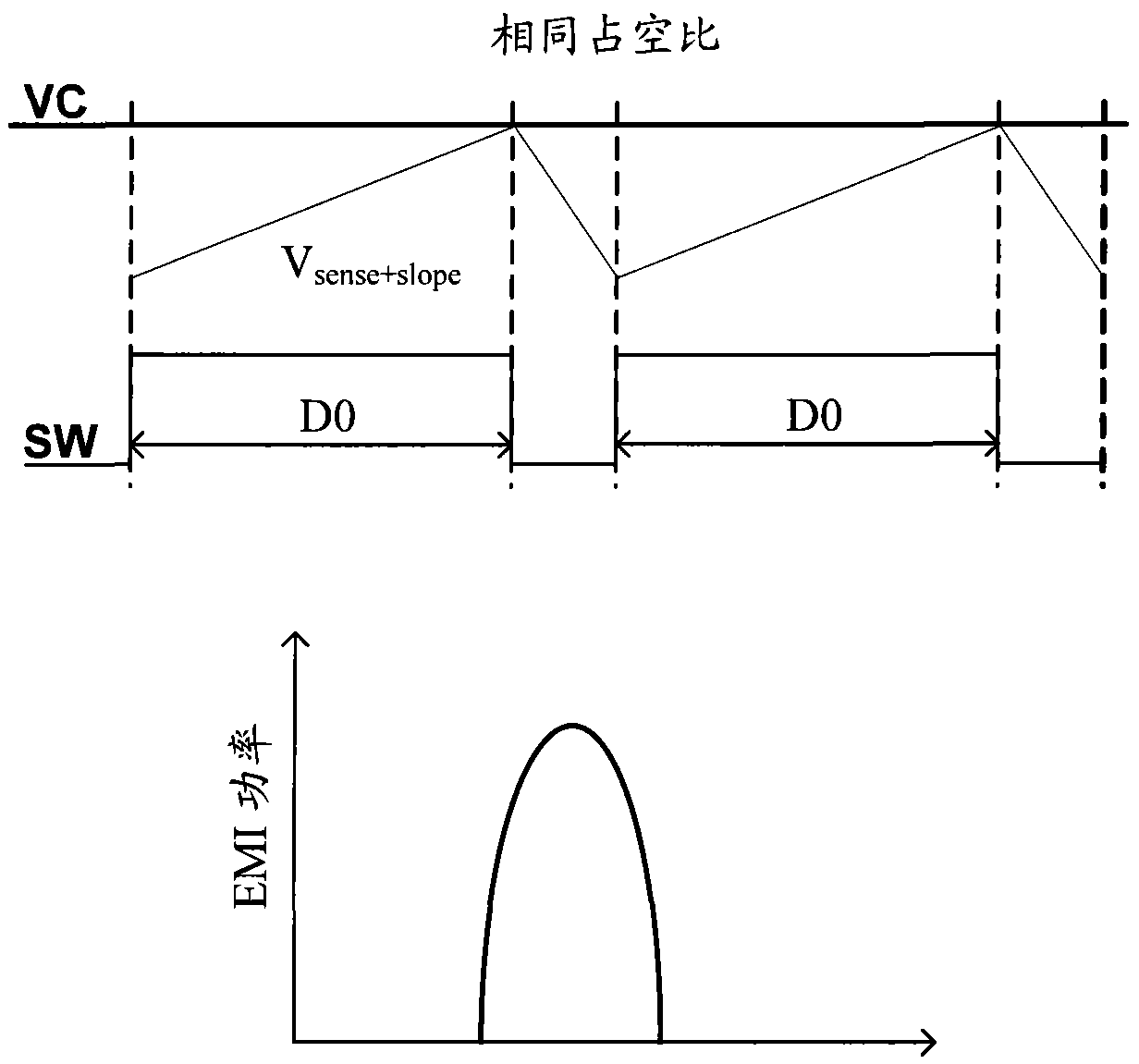
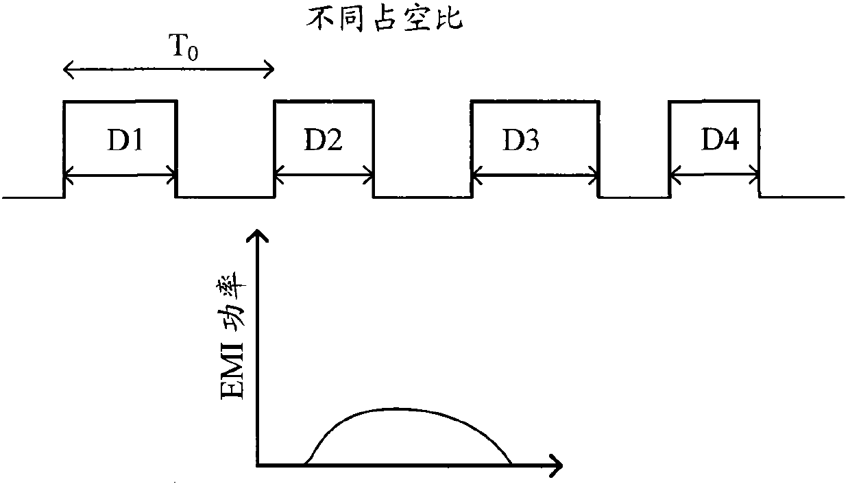
[0045] As mentioned in the Background section, a standard duty cycle will result in significant EMI power. figure 2 The relationship between dynamic duty cycle and EMI power is shown. The dynamic duty cycle can distribute the EMI energy over a wider frequency spectrum, which means that the peak value of the EMI power will be less than Figure 1b The value shown in . refer to figure 2 , the DC-DC period is T 0 , when the duty ratios of adjacent periods are different, it means that the duty ratios D1-D4 are different from each other, and the peak value of EMI power will be greatly reduced.

[0046] Figure 3a It is ...


PUM


Abstract

The invention relates to a slope voltage generator circuit which comprises a current module and a voltage converter. The current module is used for generating periodic current, values of the periodic current are different in adjacent periods at least, and the voltage converter is coupled to an output end of the current module and configured to generating periodic voltage based on the periodic current. In each period, a slope generator outputs random signals. When being used in the DC-DC converter, the random signals are overlapped on inductance detection signals to generate voltage signals Vsense+slope, and a PWM (pulse width modulation) unit of the DC-DC converter modulates duty ratio of a switch on the basis of the voltage signals Vsens+slope, so that power of EMI (electromagnetic interference) can be lowered substantially.

Description

technical field [0001] The present invention relates generally to integrated circuits and, more particularly, to peak current mode DC-DC converter circuits with spread spectrum for LED driving devices. Background technique [0002] In recent years, due to low power consumption, LEDs are widely used in electronic equipment, street lamps, factories, schools, etc. For LED devices, optical density control is very important. [0003] With the development of optoelectronic technology and semiconductor technology, flat panel displays have become popular. Among various types of flat panel displays, liquid crystal displays (LCDs) have become mainstream in the display market due to their high space utilization, low power consumption, low radiation, and low electromagnetic interference (EMI) characteristics. The LCD display includes a liquid crystal panel and a backlight module. The backlight module needs to provide a surface light source for the LCD panel to activate its display fun...

Claims


Application Information

Patent Timeline
Patent Type & Authority Patents(China)
IPC IPC(8): H02M1/44H02M3/10H05B37/02
CPCH02M3/1584
Inventor 段毅君黄涛涛
Owner STMICROELECTRONICS (SHENZHEN) R&D CO LTD
Why Eureka
Try Eureka