Set-top box

A set-top box and housing technology, applied in image communication, selective content distribution, electrical components, etc., can solve the problem that the set-top box cannot be placed on a wall-mounted TV, etc., and achieve the effect of saving cost, space and simple structure

Inactive Publication Date: 2015-05-20
XIAN PAINUO INFORMATION TECH
View PDF0 Cites 0 Cited by
  • Summary
  • Abstract
  • Description
  • Claims
  • Application Information

AI Technical Summary

Problems solved by technology

[0003] The technical problem to be solved by the present invention is to solve the defect that the existing set-top box cannot be placed on the top surface of the wall-mounted TV

Method used


Image

  • Set-top box
  • Set-top box
  • Set-top box

Examples


Embodiment Construction

[0013] In order to overcome the defect that the existing set-top box cannot be placed on the top surface of the wall-mounted TV, a set-top box will be further described in detail below with reference to the drawings and embodiments.

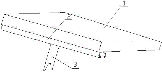
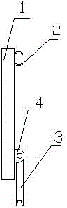
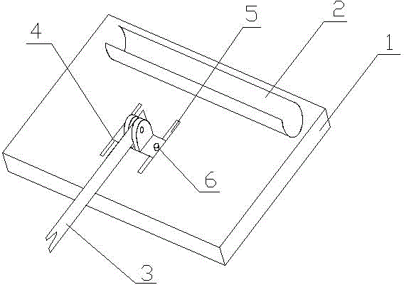
[0014] Such as figure 1 The shown set-top box includes a housing 1, the bottom front end of the housing 1 is fixedly provided with a card slot 2, the bottom rear end of the housing 1 is provided with a pole 3, and one end of the pole 3 is It is movably connected with the shell 1, and the other end has a groove. It can be seen that when the set-top box is used, the card slot 2 can be buckled to the upper edge of the wall-mounted TV. In order to stabilize the set-top box, the set pole 3 can be supported on the wall-mounted bracket of the wall-mounted TV, realizing the set-top box. The problem that can be placed on the wall-mounted TV set has a simple structure and saves use cost and use space.

[0015] Wherein, in order that the card slot 2 can b...


PUM


Abstract

The invention provides a set-top box comprising a shell. A clamping groove is fixedly arranged at the front end of the bottom of the shell; a supporting rod is arranged at the rear end of the bottom of the shell, one end of the supporting rod is movably connected to the shell, and the other end is provided with a groove. The set-top box is simple in structure and can be placed on the top of a wall-mounted television, and cost and space are saved.

Description

technical field [0001] The invention relates to a set-top box. Background technique [0002] With the popularization of digital TV, set-top boxes such as digital satellite TV set-top boxes, digital cable TV set-top boxes and digital terrestrial wave TV set-top boxes have entered the family in large numbers. At present, wall-mounted TVs are the first choice for people to choose TVs. When using a set-top box, the set-top box cannot be placed on the top of the wall-mounted TV, and the cable required to be placed elsewhere will increase the cost and affect the overall appearance. Contents of the invention [0003] The technical problem to be solved by the present invention is to address the defect that the existing set-top box cannot be placed on the top surface of the wall-mounted TV. The invention provides a set-top box which has a simple structure and can be placed on a wall-mounted television. [0004] For this reason, the present invention provides a kind of set-top box...

Claims


Application Information

Patent Timeline
IPC IPC(8): H04N21/41
CPCH04N21/41
Inventor 崔丹萍
Owner XIAN PAINUO INFORMATION TECH
Why Eureka
Try Eureka