A printed circuit board mount

A technology for printed circuit boards and mounting bases, applied in the direction of support structure installation, etc., can solve the problems of increasing creepage distance, creepage, affecting electrical performance, etc., to avoid creepage phenomenon, improve safety performance, and facilitate heat dissipation.

Inactive Publication Date: 2017-07-07
珠海超群电子科技有限公司
View PDF1 Cites 0 Cited by
  • Summary
  • Abstract
  • Description
  • Claims
  • Application Information

AI Technical Summary

Problems solved by technology

Although this product solves the problem of whether the installation and fixing of the electronic module is convenient, due to the openings formed on both sides of the main body, when multiple brackets are installed in the cabinet, there is no effective partition between the electronic modules in each bracket, which is easy to produce Creepage phenomenon, which negatively affects the performance of electronic modules
If the main structure is formed into a completely enclosed four-sided covering structure, although this can increase the creepage distance, avoid creepage phenomenon, and improve safety performance, but because the electronic module is completely enclosed, it is not conducive to heat dissipation and will also affect electrical performance.
In addition, since there are openings on both sides of the main body, the main structure can bear little force, the overall structure of the bracket is not stable enough, it is easy to deform due to force, and cannot effectively protect the electronic module.

Method used


Image

  • A printed circuit board mount
  • A printed circuit board mount
  • A printed circuit board mount

Examples


Embodiment Construction

[0020] The technical solutions of the present invention will be described below in conjunction with the accompanying drawings and embodiments.

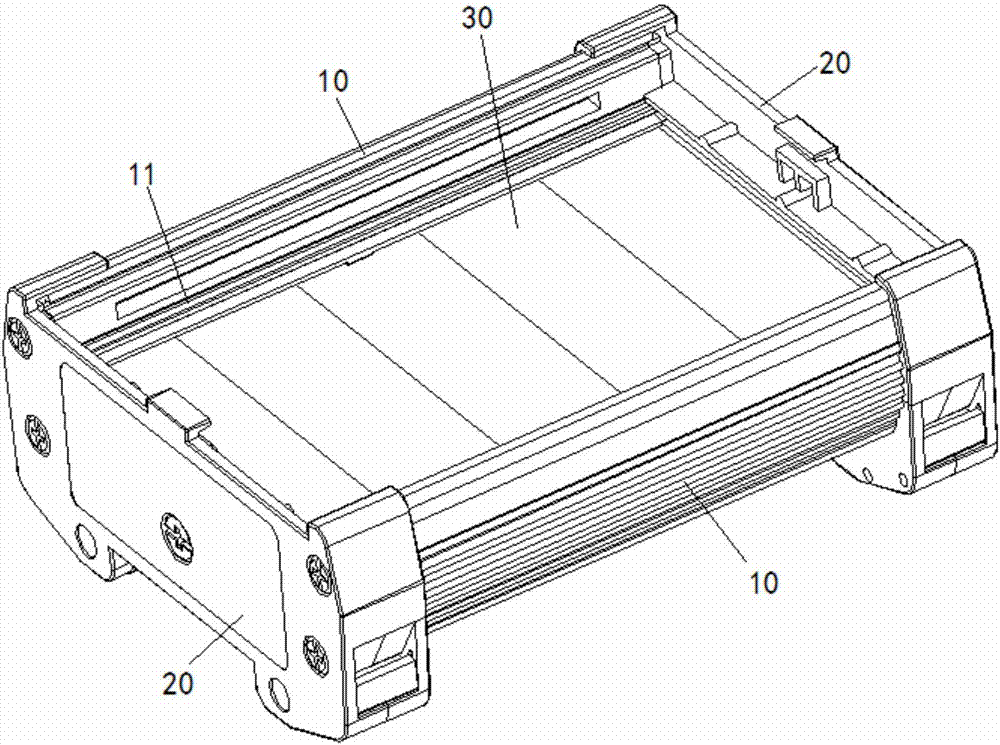
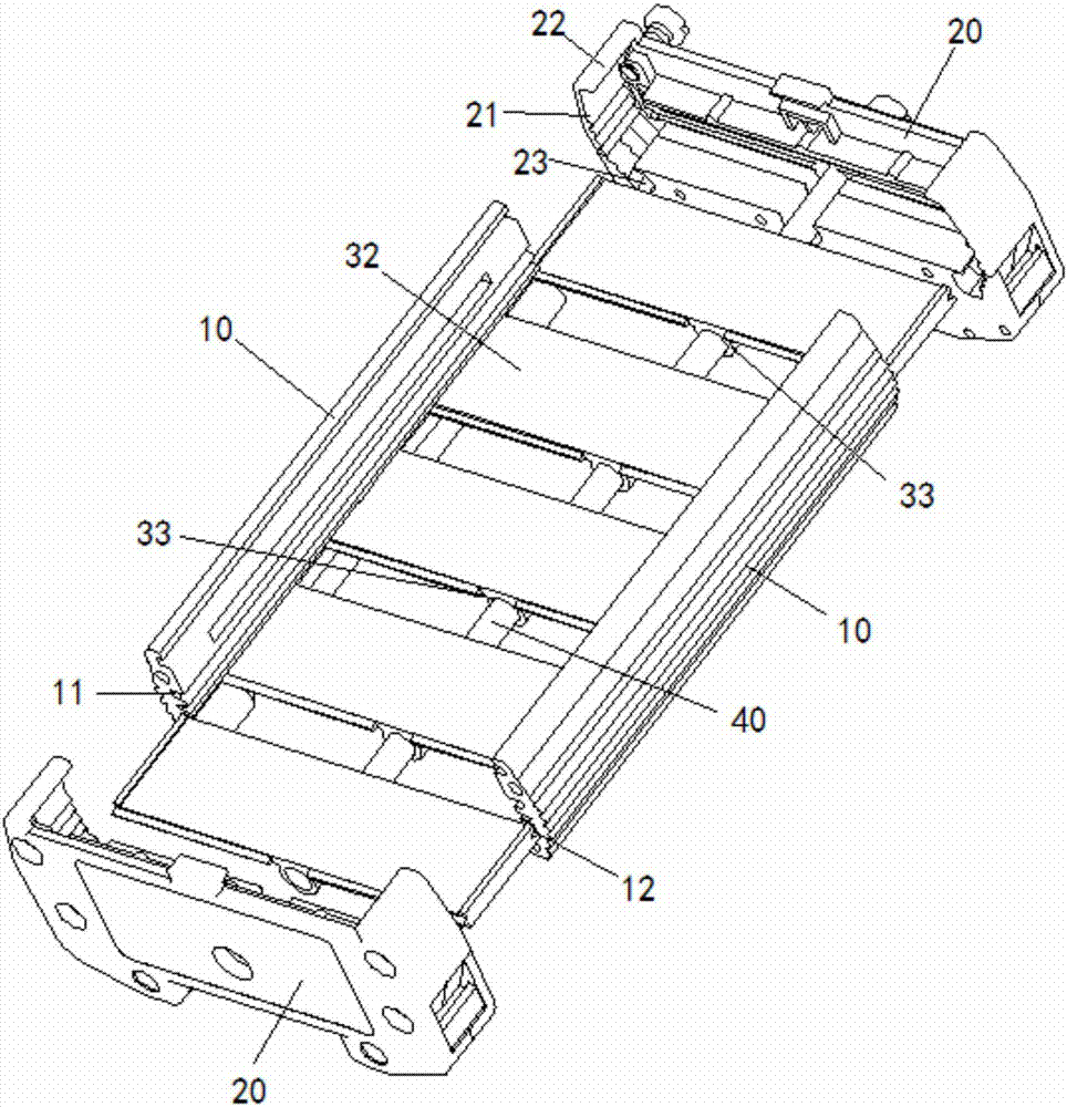
[0021] like Figure 1 to Figure 3 As shown, a printed circuit board mounting seat according to the present invention includes two side plates 10 respectively located on two opposite sides, and two ends respectively connected to the two ends of the side plates 10 and positioning the side plates 10 Cover 20, the upper inner side of the side plate 10 is provided with a chute 11 that can be installed with an electronic module circuit board, and also includes a pull rod 40 with two ends connected to the two end covers 20 respectively, and the pull rod 40 pulls Tighten the two end caps 20 to keep them close together. A guide groove 12 is provided on the inner side of the side plate 10 , and a bottom plate 30 is installed in the guide groove 12 . The bottom plate 30 includes a plurality of plates 32 , ear portions 33 are provided on the bot...


PUM


Abstract

The invention discloses a printed circuit board installation seat, which comprises two side plates (10) arranged oppositely, and two end covers respectively connected to the two ends of the side plates (10) and positioning the side plates (10). (20), the upper inner side of the side plate (10) is provided with a chute (11) for installing the circuit board carrying the electronic module, and the lower inner side of the side plate (10) is provided with an installable bottom plate (30 ) guide slot (12), also includes two ends connected to the pull rod (40) on the two end covers (20) respectively, the bottom plate (30) includes a plurality of plates (32), in each plate (32) The bottom surface is provided with ears (33), and the pull rods (40) pass through the ears (33) of each plate (32) in turn. The present invention has a stable structure and higher strength. When the distance is sufficient, the heat dissipation performance is also improved.

Description

technical field [0001] The invention relates to a printed circuit board installation seat. Background technique [0002] In industrial control systems, industrial automation and other fields, relay couplers, photocouplers, active and passive isolators, transmitters, switching power supplies, input and output interface devices, switches, isolator switches are increasingly used How to arrange such electronic modules, whether the installation is firm and reliable, and whether the operation is convenient and fast, will directly affect the quality, progress and cost of electrical engineering. [0003] In view of this, the Chinese Patent Publication No. CN203596997U mentions a circuit board support based on modular design, which adopts the cooperation of the main body and the cover of the support, and sets guide grooves in the main body to clamp the circuit board, avoiding the disadvantages of screw fixing , can reduce the accident rate and improve product reliability. Although ...

Claims


Application Information

Patent Timeline
Patent Type & Authority Patents(China)
IPC IPC(8): H05K7/14
Inventor 潘志俊李战领赵万方
Owner 珠海超群电子科技有限公司
Why Eureka
Try Eureka