Foam Processing Equipment

A processing equipment and foam technology, which is applied in the field of foam processing, can solve problems such as easy cracking of foam, and achieve the effect of high safety and simple structure

Inactive Publication Date: 2016-08-24
CHONGQING WEIFENG PLASTIC PROD
View PDF11 Cites 0 Cited by
  • Summary
  • Abstract
  • Description
  • Claims
  • Application Information

AI Technical Summary

Problems solved by technology

[0005] When the foam processing equipment of the present invention is in use, the foam is pre-compressed through the stripping plate, and then the drill bit passes through the through hole of the stripping plate to process on the foam, so that the foam has a buffering process in advance during processing. Solve the technical problem that the foam is easy to crack during processing in the prior art to a certain extent

Method used


Image

  • Foam Processing Equipment
  • Foam Processing Equipment
  • Foam Processing Equipment

Examples


Embodiment Construction

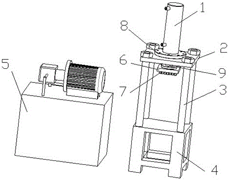
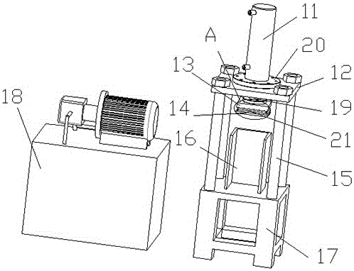
[0018] Please refer to image 3 , image 3 It is a structural schematic diagram of the foam processing equipment of the present invention. The foam processing equipment includes: an oil pump assembly 18, a hydraulic cylinder 11, a press upper plate 12, a discharge plate 14, an upper die 13, a press lower plate 16, several pillars 15 and a base 17. The oil pump assembly 18 It is connected with the hydraulic cylinder 11 and is used to provide power for the hydraulic cylinder 11. The upper platen 12 of the press is fixed on the base 17 through several pillars 15, and the telescopic rod 19 of the hydraulic cylinder 11 passes through the center hole of the upper platen 12 of the press, and is fixedly connected with the upper platen 12 of the press through a connecting piece 20 . The telescopic rod 19 is connected with the upper mold 13 . The lower platen 16 of the press is arranged directly below the unloading plate 14 for fixing the foam to be processed.

[0019] Please refer...


PUM


Abstract

The invention relates to foam processing equipment, which comprises an oil pump assembly (18), a hydraulic oil cylinder (11), a press upper table plate (12), an upper die (13), a plurality of support columns (15), a base (17) and a material discharging plate (14), wherein the material discharging plate (14) is connected with the upper die (13) through an elastic structure, a plurality of through holes are formed in the material discharging plate (14), and a drill bit (21) penetrates through the through holes to process. The foam processing equipment solves the technical problem of easy cracking of foam when the foam is processed by the foam processing equipment of the prior art.

Description

technical field [0001] The invention relates to foam processing equipment, which belongs to the field of foam processing. Background technique [0002] Please refer to figure 1 , figure 1 It is a structural schematic diagram of foam processing equipment in the prior art. The foam processing equipment in the prior art includes an oil pump assembly 5 , a hydraulic cylinder 1 , an upper platen 2 of a press, several pillars 3 , a base 4 and an upper mold 6 . The oil pump assembly 5 is connected with the hydraulic cylinder 1 to provide power for the hydraulic cylinder 1 . The upper platen 2 of the press is fixed on the base 4 through several pillars 3, the telescopic rod 9 of the hydraulic cylinder 1 passes through the center hole of the upper platen 2 of the press, and is fixedly connected with the upper platen 2 of the press through a connecting piece 8 . The telescopic rod 9 is connected with the upper mold 6 . Several drill bits 7 are fixed on the upper mold 6 . Please...

Claims


Application Information

Patent Timeline
Patent Type & Authority Patents(China)
IPC IPC(8): B26F1/16B26D7/02
CPCB26D7/025B26F1/16
Inventor 邹武
Owner CHONGQING WEIFENG PLASTIC PROD
Why Eureka
Try Eureka