Concrete transfer device

A transfer device and concrete technology, applied in the directions of transportation, packaging, loading/unloading, etc., can solve the problems of low safety and difficult construction, and achieve the effect of convenient operation, avoiding pipe blockage and less disturbance.

Active Publication Date: 2015-05-27
CCCC SECOND HARBOR ENG
View PDF6 Cites 7 Cited by
  • Summary
  • Abstract
  • Description
  • Claims
  • Application Information

AI Technical Summary

Problems solved by technology

[0004] The purpose of the present invention is to solve the deficiencies of the above-mentioned background technology, and provide a concrete transfer device, which can solve the problems of difficult construction and low safety of conventional technical means

Method used


Image

  • Concrete transfer device
  • Concrete transfer device
  • Concrete transfer device

Examples


Embodiment Construction

[0020] The present invention will be further described in detail below in conjunction with the accompanying drawings and specific embodiments.

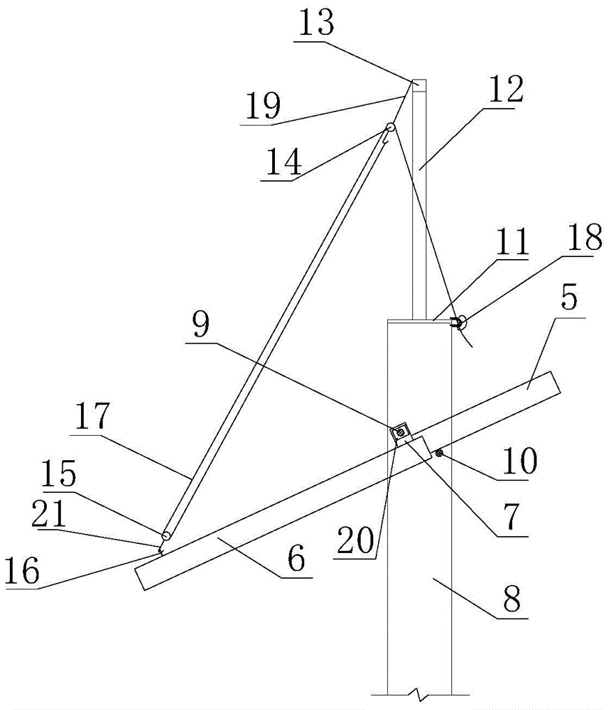
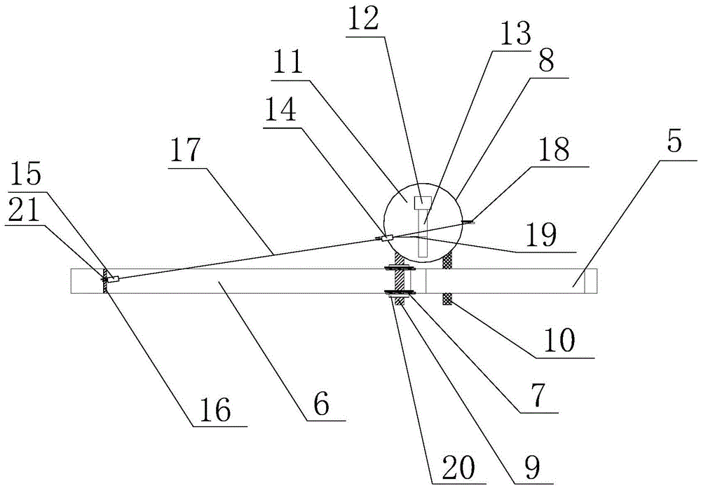
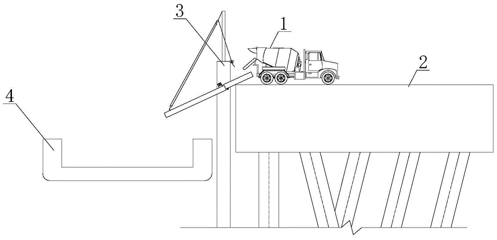
[0021] refer to figure 1 and figure 2 , a concrete transfer device of the present embodiment mainly includes steel pipe piles 8 and chutes, the steel pipe piles 8 are arranged outside the edge of the wharf 2, steel cover plates 11 are welded on the top surface of the steel pipe piles 8, and the uprights 12 are welded On the steel cover plate 11, the cross bar 13 is welded on the column 12. The chute of the present embodiment comprises an upper section chute 5 and a lower section chute 6 that are all semicircular steel pipes. On the support rod 10 below the platform, through the joint action of the support rod 10 and the corners of the wharf, the upper section chute 5 forms a fixed inclination angle; the lower end of the upper section chute 5 is docked with the upper end of the lower section chute 6. Just below the lower end of the...


PUM


Abstract

The invention discloses a concrete transfer device. The concrete transfer device comprises a steel pipe pile and a sliding chute, wherein an upright post is fixedly arranged on the top of the steel pipe pile, and a cross rod is fixedly arranged on the top of the upright post; one end of the sliding chute is put on the corner of a wharf, and the other end of the sliding chute extends downwards slantly and is connected with the cross rod through a suspension device. When the concrete transfer device is used, a concrete tank car positioned on the wharf is used for discharging concrete inside the upper section of the sliding chute, the concrete flows towards the lower section of the sliding chute along the upper section of the sliding chute and finally flows in the cabin of a transport ship, and after the cabin is filled with the concrete, the transport ship can drive away from the transfer device. The concrete is transported to the transport ship by adopting the sliding chute, the disturbance on the concrete is little, the performance of the concrete is not changed, the phenomenon of pipe blockage can further be avoided, the device is free of hoisting operation, the safety is guaranteed, and the concrete transfer device is simple in structure and convenient in operation and has great promotional value.

Description

technical field [0001] The invention relates to the field of concrete construction on water, in particular to a concrete transfer device. Background technique [0002] When carrying out concrete construction on water, it is often necessary to mix concrete on land first, and then transfer it to the point to be poured by a transport ship for concrete pouring. The common way to transfer concrete from the land to the transport ship is to set up a concrete boom on the shore, and use the boom to pump the concrete into the cabin; or put the concrete into the tank, and use the lifting equipment to lift the tank to the transport on board. [0003] The method of pumping with the boom will greatly disturb the concrete, easily change the performance of the concrete, and also easily cause the problem of pipe plugging. With the method of material tank, the amount of concrete transported by each ship is limited, and there is a lifting operation, which has great potential safety hazards. ...

Claims


Application Information

Patent Timeline
Patent Type & Authority Applications(China)
IPC IPC(8): B65G69/28B65G67/60
CPCB65G67/606B65G69/2805
Inventor 唐蔚东向继华谭永安齐应明
Owner CCCC SECOND HARBOR ENG
Why Eureka
Try Eureka