
Construction method for temporary horizontal supports serving as permanent structural beams simultaneously of deep foundation pit

A technology of horizontal support and permanent structure, which is applied in basic structure engineering, underwater structure, water conservancy engineering and other directions, can solve the problems of a large amount of construction waste, difficult to control the deformation of foundation pit, self-heavy and other problems

Active Publication Date: 2015-05-27
SHANGHAI ERSHIYE CONSTR CO LTD +1
View PDF4 Cites 13 Cited by
  • Summary
  • Abstract
  • Description
  • Claims
  • Application Information

AI Technical Summary

Problems solved by technology

[0003] Steel support is especially suitable for small excavation area, short construction period, and elongated foundation pits (such as subway stations, etc.); Control pit deformation
[0004] Reinforced concrete support is suitable for foundation pits with large area, deep depth, long construction period and complex geological conditions; it has the advantages of good stability, high adaptability, and small foundation pit deformation, but its own weight is relatively large, and the main structure of the underground After the construction is completed, it needs to be demolished by machinery or blasting, which will generate a lot of construction waste and cause a waste of resources

Method used


Image

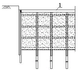
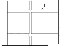
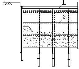
  • Construction method for temporary horizontal supports serving as permanent structural beams simultaneously of deep foundation pit
  • Construction method for temporary horizontal supports serving as permanent structural beams simultaneously of deep foundation pit
  • Construction method for temporary horizontal supports serving as permanent structural beams simultaneously of deep foundation pit

Examples


Embodiment Construction

[0021] The present invention is further illustrated below by specific examples.

[0022] For a foundation pit project, the area of ​​the foundation pit is more than 70,000 square meters, the average excavation depth is 17.9 meters, and there are three underground floors. The underground diaphragm wall is used as the enclosure and water-stop structure. There are three horizontal supports for the foundation pit, and the construction method of "temporary horizontal support for deep foundation pit double as permanent structural beam" is adopted. The specific steps are as follows:

[0023] The first step is to determine the position (vertical and plane), cross-sectional size, reinforcement and concrete strength of the reinforced concrete temporary horizontal support double as the permanent structural beam after design check and calculation, so that it can meet the requirements of the supporting enclosure structure and the main body of the basement at the same time. Structural force...


PUM


Abstract

The invention particularly relates to a construction method for temporary horizontal supports serving as permanent structural beams simultaneously of a deep foundation pit. The method is characterized by comprising the steps of determining the position and parameters of the reinforced concrete temporary horizontal supports serving as permanent structural beams simultaneously; excavating first-layer earthworks, and constructing the first reinforced concrete temporary horizontal support; excavating the earthworks till the bottom elevation position of the second reinforced concrete temporary horizontal support, constructing the horizontal support, reserving reinforcing ribs on the horizontal support according to design requirements, constructing the third and lower horizontal supports till the foundation pit excavation is completed and bottom plate pouring is completed; connecting the reinforcing ribs reserved on the temporary horizontal supports with corresponding basement floor reinforcing ribs to form a whole, and manufacturing permanent structures of basement floors and the like; dismounting the first horizontal support; backfilling the foundation pit to complete construction. By the aid of the method, compared with a traditional forward building method, lots of building rubbish and high construction expenditures caused by later dismounting of the horizontal supports are saved through the steps.

Description

technical field [0001] The invention relates to the field of deep foundation pit construction, in particular to a construction method in which the temporary horizontal support of a deep foundation pit doubles as a permanent structural beam. Background technique [0002] The earthwork excavation of the foundation pit in the forward (sequent) method is generally carried out in accordance with the principles of layering, division, and symmetry, and the horizontal support system is constructed in time after the excavation of each block or layer of earthwork is completed. After the earth excavation is completed, the underground structure will be constructed layer by layer from bottom to top and the corresponding temporary supports will be removed. Horizontal temporary support generally takes the form of steel support or reinforced concrete support. [0003] Steel support is especially suitable for small excavation area, short construction period, and elongated foundation pits...

Claims


Application Information

Patent Timeline
IPC IPC(8): E02D17/02E02D29/045
CPCE02D17/02E02D17/04E02D2220/00
Inventor 岳齐贤赵建立梁勇温克彬于青川
Owner SHANGHAI ERSHIYE CONSTR CO LTD
Learn More