
A wind heat pressure induced multi-channel ventilation and heat insulation system

A multi-channel and channel technology, applied in vertical pipes, building components, thermal insulation, etc., can solve the problems of ineffective and reasonable utilization of outdoor wind, insufficient solar energy inducing ability, and increased maintenance and repair difficulty, achieving good application prospects, strengthening Natural ventilation capacity, significant energy saving effect

Active Publication Date: 2017-03-29
TAIYUAN UNIV OF TECH
View PDF8 Cites 0 Cited by
  • Summary
  • Abstract
  • Description
  • Claims
  • Application Information

AI Technical Summary

Problems solved by technology

[0004] Traditional solar chimneys can enhance the natural ventilation of buildings through thermal buoyancy, but there are still deficiencies, as follows: (1) The actual solar chimneys will inevitably be affected by wind force, and even the wind force will affect its performance. Weakening and inhibition, the traditional solar chimney does not consider the influence of the outdoor wind speed, nor does it effectively and rationally utilize the effect of the outdoor wind; (2) The ventilation form of the traditional Trombe wall structure sets an air channel, and its heat-absorbing part is set on the outer wall of the building , the heat insulation effect is not good, which increases the indoor cooling load
The traditional solar ventilation system uses solar energy only on the heat absorbing layer, and the solar induction ability is insufficient; (3) Although the solar ventilation system using solar panels and fans does not consume other forms of energy, it involves more circuit components, equipment and investment, and the system Complexity, increased maintenance and repair difficulty

Method used


Image

  • A wind heat pressure induced multi-channel ventilation and heat insulation system
  • A wind heat pressure induced multi-channel ventilation and heat insulation system
  • A wind heat pressure induced multi-channel ventilation and heat insulation system

Examples


Embodiment approach 1

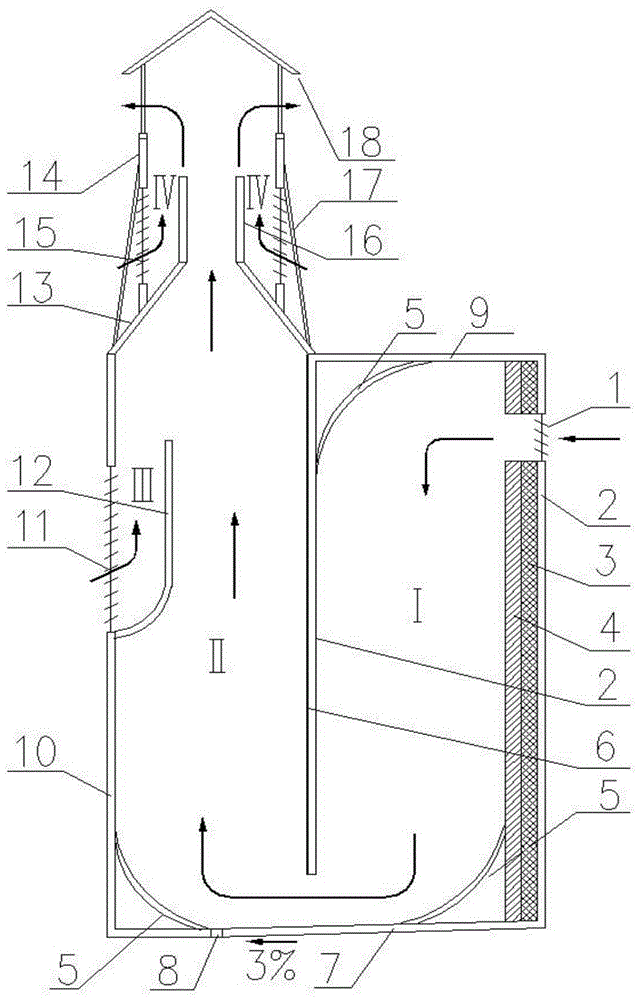
[0039] refer to figure 1 As shown, the present invention includes two main airflow passages I, II and two outdoor air induction passages III, IV, wherein the main airflow passage I is set between the heat insulation layer 4 and the left partition 2, and the main airflow passage II is set Between the heat-absorbing layer 6 and the glass cover plate 10, 1 is the louver tuyere, and there is an insulating layer 3 and a right partition 2 on the outer side of the heat-insulating layer 4 of the main airflow channel I, and a deflector 5 is arranged on the top top plate 9, Above the channels I and II are the top plate 9 and the sky round place 13 respectively. Below the channels I and II, deflectors 5 are set and fixed on the bottom plate 7. The bottom plate is provided with a sealing rubber strip 8, and the heat-absorbing layer is coated with black chrome. The thickness of the coating is 0.18mm, the insulation layer is made of rubber and plastic, the thickness is 25mm, the heat insula...

Embodiment approach 2

[0053] refer to figure 1 As shown, the present invention includes two main airflow passages I, II and two outdoor air induction passages III, IV, wherein the main airflow passage I is set between the heat insulation layer 4 and the left partition 2, and the main airflow passage II is set Between the heat-absorbing layer 6 and the glass cover plate 10, 1 is the louver tuyere, and there is an insulating layer 3 and a right partition 2 on the outer side of the heat-insulating layer 4 of the main airflow channel I, and a deflector 5 is arranged on the top top plate 9, Above the channels I and II are the top plate 9 and the sky round place 13 respectively. Below the channels I and II, deflectors 5 are set and fixed on the bottom plate 7. The bottom plate is provided with a sealing rubber strip 8, and the heat-absorbing layer is coated with black chrome. The thickness of the coating is 0.18mm, the insulation layer is made of rubber and plastic, the thickness is 25mm, the heat insula...

Embodiment approach 3

[0067] refer to figure 1 As shown, the present invention includes two main airflow passages I, II and two outdoor air induction passages III, IV, wherein the main airflow passage I is set between the heat insulation layer 4 and the left partition 2, and the main airflow passage II is set Between the heat-absorbing layer 6 and the glass cover plate 10, 1 is the louver tuyere, and there is an insulating layer 3 and a right partition 2 on the outer side of the heat-insulating layer 4 of the main airflow channel I, and a deflector 5 is arranged on the top top plate 9, Above the channels I and II are the top plate 9 and the sky round place 13 respectively. Below the channels I and II, deflectors 5 are set and fixed on the bottom plate 7. The bottom plate is provided with a sealing rubber strip 8, and the heat-absorbing layer is coated with black chrome. The thickness of the coating is 0.18mm, the insulation layer is made of rubber and plastic, the thickness is 25mm, the heat insula...


PUM


Abstract

The invention discloses a wind hot pressure induced multichannel ventilating and insulating system and belongs to the technical field of ventilation equipment for residential and public buildings. The wind hot pressure induced multichannel ventilating and insulating system is characterized in that the wind hot pressure inducing action of solar energy and wind energy as renewable energy sources is effectively utilized, so that electric energy is prevented from being consumed, the quality of indoor air can be guaranteed, and the energy-saving effect is remarkable while the natural ventilation capability is enhanced. According to the system, natural ventilation is formed by fully utilizing the inducing action of hot pressure and wind pressure which are respectively generated by the solar energy and the wind energy; meanwhile, indoor load is reduced, the energy consumption for buildings is greatly reduced, and the quality of the indoor air is effectively improved. The wind hot pressure induced multichannel ventilating and insulating system has the advantages of good ventilation effect, energy conservation, environmental protection, easiness for assembly and convenience for assembly and disassembly, and can be widely applied to common civil buildings and large-scale industrial buildings.

Description

technical field [0001] The invention relates to a wind-heat-pressure-induced multi-channel ventilation and heat insulation system, which belongs to the technical field of ventilation equipment for residences and public buildings, and specifically relates to a wind-heat-pressure induction effect that effectively utilizes two renewable energy sources, solar energy and wind energy. The multi-channel ventilation and heat insulation system with extremely remarkable energy-saving effect can ensure the indoor air quality without consuming electric energy while providing natural ventilation. Background technique [0002] With the development of building technology and the increasing scarcity of non-renewable energy sources, the problem of high energy consumption in buildings has become increasingly prominent, and the proportion of building energy consumption in total energy consumption is also increasing. In developed countries, nearly 40% of energy is consumed in buildings; in my c...

Claims


Application Information

Patent Timeline
Patent Type & Authority Patents(China)
IPC IPC(8): E04F17/04E04B1/76
Inventor 雷勇刚王飞顾元段绍阳赵文博
Owner TAIYUAN UNIV OF TECH
Learn More